Vermes
Advanced Member level 4
Assumptions:
- control of compressor and circulation pumps
- acting as pump protection
- reading and processing the temperatures that are necessary for the operation of the pump and additional ones with high accuracy
- control the operation of the pump, depending on outdoor and indoor temperatures
- heating in the low fare and heating to a specific time (fixed hour when the pump stops working)
- write all events in a nonvolatile memory (inclusion, exclusion, failures and errors) and statistics (daily temperatures, energy consumption)
- control of piezoelectric CO valves
- control over the network
Part A – functionality
Protection: The driver cooperates with external pressure sensors (pressure switches), failure and phase sequence sensor. In the event of activating one of those sensors, the compressor is switched off via an external relay and the microprocessor cuts off the triac which controls the compressor. It is in some sensea dual protection. All temperature protections are controlled only by the microprocessor.
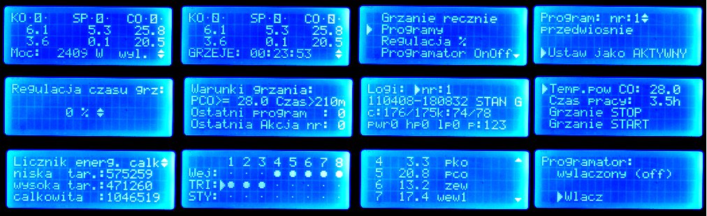
Heating programs: The driver realizes one of the 16 heating programs. Each program consists of maximum 32 items, and each item is programmed by the hour and day of the week operation such as start of heating. Additionally, each operation may depend on temperature and input status. The length of heating may depend on temperatures. The most important feature is heating 'until the hour', what is crucial at the low fare. In the morning, the pump is off exactly at the hour which ends a low fare. Any operation may turn on one of 5 inputs that control AC circuits (230V) or 8 opto-contactors AC/DC. Thus, at the end of these steps, some of the valves can be attached (normally open) on the manifolds and warm up for example a bathroom. One program is solid (always executes) and is used to program such as fare or other devices. The driver is also equipped with adjustable “thermostat” when using heat pump for hot water.
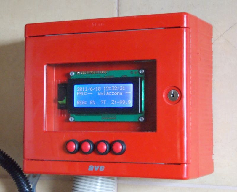
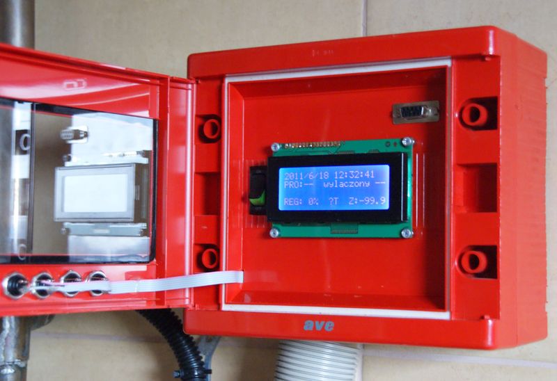
Control: Like any driver, the driver is equipped with a display. The following pictures show a number of different functions of the display. Four buttons are used to control the device. Using this interface, in addition to activities related to the normal operation of the pump, there is also several service functions, such as manual control of the control circuit or manual switching the circulators.
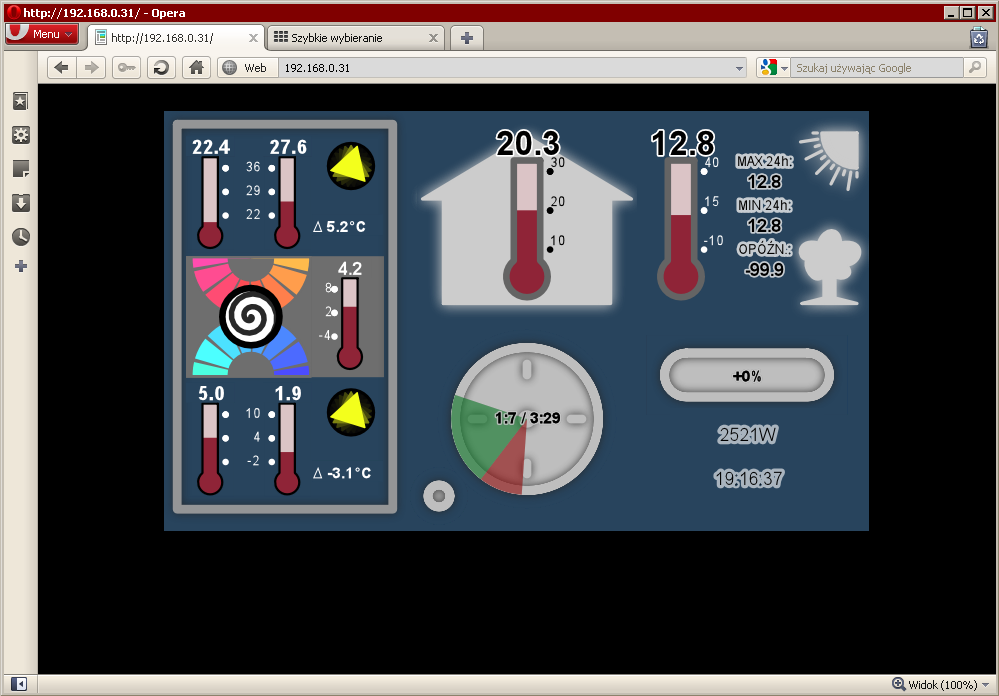
The main programming, configuration and maintenance activities such as “'logs” reading is done by command line tool (Linux / Windows / MAC). Heating settings and programs are stored as XML files. Configuration tool reads these XML files and configures the driver. In addition, all information from the driver can be presented in the form of “human” or XML. Using the XML interface is aimed mainly to integrate with the Web server. In this project, for safety reasons, Web page was not put in the driver. The driver was to control the pump and protection. The solution for user-friendly interface is a Web server in the home network, that uses a configuration tool while pages generation to obtain information in the form of a friendly Web page. In addition, the home server periodically generates by using XML status file and sends it to an external server via FTP, which is publicly available along with a website (see picture below).
Part B - Construction
The heart of the driver is a module with microprocessor ST STR912FAW44 (ARM966E-S). The module has a built-in Ethernet interface, 8MB SPI flash memory. The software is written in C and the operating system is FreeRTOS. As the IP stack, uIP was used.
DS1820 are temperature sensors. With enhanced accuracy, they give reading with accuracy of 1/16C. There can be maximum 12 sensors and they can be connected to three different ports: two 1W on the plate and one RS232C (RS232C as a transmission and a small adapter next to the sensor).
Control of external systems is via ULN2803 systems, that connect LEDs in opto-isolators. The first eight outputs are separated by optotriacs MOC3063 triacs. Compressor relay and circulation pumps are powered from those outputs (circulation pumps directly). The second eight outputs are opto-contactors AQV214 or AQV414 (normally closed), 0,12A maximum current is sufficient to drive the pizoelectric 5W valves. Input circuits, at a given voltage of 24V control circuit, are two optocouplers of 4-inputs PS2501-4.
The whole is powered by the system LM2672 (5V) and LM2937 (3,3V).

Link to original thread – Sterownik Pompy Ciepła