Continue to Site

Welcome to EDAboard.com

Welcome to our site! EDAboard.com is an international Electronics Discussion Forum focused on EDA software, circuits, schematics, books, theory, papers, asic, pld, 8051, DSP, Network, RF, Analog Design, PCB, Service Manuals... and a whole lot more! To participate you need to register. Registration is free. Click here to register now.

[SOLVED] Division Circuit in VHDL

Status
Not open for further replies.

ss_reddy23

Newbie level 6
Joined
Oct 1, 2020
Messages
11
Helped
1
Reputation
2
Reaction score
0
Trophy points
1
Activity points
121
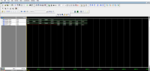
I'm trying to design 4 bit division circuit and used a comparison and subtraction technique to reach the answer. The logic is correct but the code has some bugs. The waveform is not correct. Can someone look into the code and waveform and say whats the problem is

Code VHDL - [expand]
1
2
3
4
5
6
7
8
9
10
11
12
13
14
15
16
17
18
19
20
21
22
23
24
25
26
27
28
29
30
31
32
33
34
35
36
37
38
39
40
41
42
43
44
45
46
47
48
49
50
51
52
53
54
55
56
57
58
59
60
61
62
63
64
65
66
67
68
69
70
71
72
73
74
75
76
77
78
79
80
81
82
83
library ieee;
use ieee.std_logic_1164.all;
use ieee.numeric_std.all;
 
entity division is
  port(
 
       y,d:in std_logic_vector(3 downto 0);
         q,r:eek:ut std_logic_vector(3 downto 0)
 
  );
end division;
 
architecture divider_arch of division is
    signal y_dummy: std_logic_vector(3 downto 0);
     signal d_dummy: std_logic_vector(3 downto 0);
   
    signal p4: std_logic_vector(6 downto 0);
     signal p3: std_logic_vector(6 downto 0);
    signal p2: std_logic_vector(6 downto 0);
    signal p1: std_logic_vector(6 downto 0);
    signal p0: std_logic_vector(6 downto 0);
   
     signal d5: std_logic_vector(6 downto 0);
    signal d4: std_logic_vector(6 downto 0);
    signal d3: std_logic_vector(6 downto 0);
    signal d2: std_logic_vector(6 downto 0);
    signal d1: std_logic_vector(6 downto 0);
    
     signal q_dummy:std_logic_vector(3 downto 0);
    signal r_dummy:std_logic_vector(3 downto 0);
 
begin
y_dummy <=y;
d_dummy <=d;
p4<="000" & y_dummy;
d4<=d_dummy & "000";
d3<='0' & d_dummy & "00";
d2<="00" & d_dummy & '0';
d1<="000" & d_dummy;
 
process(y,d)
begin
 
if(p4>=d4) then
    p3<= std_logic_vector(unsigned(p4(6 downto 0)) - unsigned(d4(6 downto 0)));
    q_dummy(3)<='1';
  else
      p3<=p4;
       q_dummy(3)<='0';
end if;      
if(p3>=d3) then
              p2<= std_logic_vector(unsigned(p3(6 downto 0)) - unsigned(d3(6 downto 0)));
            q_dummy(2)<='1';
  else
          p2<=p3;
           q_dummy(2)<='0';
  end if;          
 
  if(p2>=d2) then
              p1<= std_logic_vector(unsigned(p2(6 downto 0)) - unsigned(d2(6 downto 0)));
                q_dummy(1)<= '1';
    else
              p1<=p2;
               q_dummy(1)<='0';
   end if;              
  if(p1>=d1) then
                  p0<= std_logic_vector(unsigned(p1(6 downto 0)) - unsigned(d1(6 downto 0)));
                  q_dummy(0)<='1';
                  r_dummy<= p0(3)&p0(2)&p0(1)&p0(0);
                else
                p0<=p1;
                  q_dummy(0)<='0';
                  r_dummy<= p0(3)&p0(2)&p0(1)&p0(0);
    end if;
         
   
end process;
 
q<=q_dummy;
r<=r_dummy;
 
end divider_arch;


Attachments

  • 1601521629655.png
    1601521629655.png
    185.7 KB · Views: 117
Last edited by a moderator:

The logic is correct but the code has some bugs. The waveform is not correct.

I'm afraid you can't have it both ways. If the logic is correct then, by definition, IT HAS NO BUGS.

I haven't looked that closely at your code, but two things stand out to me:

1) Why isn't this a clocked process?
2) Why aren't there any comments?

You can't expect someone to look at your code and just figure out what you're trying to do without a few hints. In fact, when you go back and look at this in a few months, even you won't know what you were thinking when you wrote. How on earth do you expect us to know what your waveform is supposed to be? What's driving those signals? Nothing I can see.

And what the heck is this?
q,r:eek:ut std_logic_vector(3 downto 0)
 

The process is sensitive only to y and d, which aren't used in the process. Expect simulation problems ...
 

Well worse yet the simulation usually shows something entirely different than the logic that synthesis will produce when your sensitivity list uses signals that aren't even used in the process. Synthesis ignores the sensitivity lists.
 

The process is sensitive only to y and d, which aren't used in the process. Expect simulation problems ...
In process do we need to use all the variable declared ? I'm just confused .
 

In process do we need to use all the variable declared ? I'm just confused .
Have you referred to a good VHDL tutorial? That should answer the above question on how sensitivity list works.


I think you should also learn on how to write sequential and combinatorial logic.
 

I made changes to my process sensitivity list and it worked. Thanks
 

I made changes to my process sensitivity list and it worked. Thanks
It would be better if you showed us what you did, as you may have "fixed" the simulation, but have code that would never synthesize properly.
 

Status
Not open for further replies.

Part and Inventory Search

Welcome to EDABoard.com

Sponsor

Back
Top