Continue to Site

Welcome to EDAboard.com

Welcome to our site! EDAboard.com is an international Electronics Discussion Forum focused on EDA software, circuits, schematics, books, theory, papers, asic, pld, 8051, DSP, Network, RF, Analog Design, PCB, Service Manuals... and a whole lot more! To participate you need to register. Registration is free. Click here to register now.

Disconnecting load from battery while charging the battery

Status
Not open for further replies.

Johnny101

Member level 1
Joined
Jul 13, 2014
Messages
34
Helped
0
Reputation
0
Reaction score
0
Trophy points
6
Activity points
356
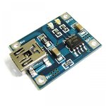
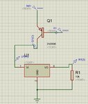
I am designing a switching circuit that disconnects the load from battery when it is charging and connects battery back to load after charging is removed. I am doing this with the help of PNP and I am using TP4056 battery charging module.In the figure attached, IN+ (5V input from USB is applied at base of PNP), bat+ (output voltage for battery charging module and battery's +ve terminal is connected at emitter), Collector is connected to voltage regulator (3.3V regulator). Battery is of 3.7V.

When 0V (in case charging is disconnected) applied at IN+ (base of PNP) then PNP should operate in active mode and 3.7V should appear on emitter as well as on collector but don't know why collector (connected to voltage regulator's input) shows 2.5V?. I think voltage regulator is loading the PNP but can't understand?
 

Attachments

  • Circuit.JPG
    Circuit.JPG
    54.3 KB · Views: 134
  • Mini USB Lithium Battery Charging Board Charger Module 5V 1A-1500x1500.jpg
    Mini USB Lithium Battery Charging Board Charger Module 5V 1A-1500x1500.jpg
    273.5 KB · Views: 82

PNP should operate in active mode and 3.7V should appear on emitter as well as on collector
Impossible, there must be a voltage drop between emitter and collector. Datasheet shows for little collector current and base current maximum 0.4 V but there, I guess, you have more current so it is expected more voltage drop.
Your emitter to base voltage is 3.7 V so you can expect more voltage drop between emitter and collector (1.2 V is reasonable I guess even without knowing your currents).
 

You have nothing to limit the base current of the transistor when IN+ goes to 0V somehow when charging is disconnected so it will blow up. Instead, maybe IN+ has a resistor to ground to turn on the transistor when the USB is disconnected.
The important input and output capacitors of the voltage regulator are missing.
When the battery voltage drops to 3.0V or 3.2V then the voltage regulator will not work. It also might not work when the battery is 3.7V unless it is a low-dropout type.
 

This makes sense?

Yes, a relay is probably the simplest and safest method.

Question: You have an On/Off switch at left. Is it manual, or does it represent a signal of some kind?

By the way, as an alternate connection, consider putting the battery at the center terminal of the DPST, and allow the relay to select either load or charger. That way they can never combine simultaneously if an unforeseen circumstance occurs.
 

Status
Not open for further replies.

Part and Inventory Search

Welcome to EDABoard.com

Sponsor

Back
Top