Continue to Site

Welcome to EDAboard.com

Welcome to our site! EDAboard.com is an international Electronics Discussion Forum focused on EDA software, circuits, schematics, books, theory, papers, asic, pld, 8051, DSP, Network, RF, Analog Design, PCB, Service Manuals... and a whole lot more! To participate you need to register. Registration is free. Click here to register now.

Diode Ciruit electronics 3

Status
Not open for further replies.

paulmdrdo

Full Member level 3
Joined
Jan 17, 2014
Messages
183
Helped
1
Reputation
2
Reaction score
2
Trophy points
18
Activity points
1,394
determine the voltage across the diode. assume complete model.

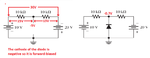
can you tell me which path will the current flow in this circuit? and how can you redraw it for easy analyzation.
elecs 4.png

this is how i redraw the equivalent circuit. tell me if it's correct. thanks!

elecs 5.png
 
Last edited:

I would remove the diode to see the polarity made by the batteries and resistors. Then I can see if the diode is forward or reverse biased. It is forward-biased.
Each battery is discharged by the diode.
 

Attachments

  • diode circuit.png
    diode circuit.png
    11 KB · Views: 85

how do you get the -5v in the middle in your first diagram? and is my 2nd configuration #1 post correct? if not can you tell why. thanks!
 
Last edited:

:-? can you show me the formula for that -5v. I'm still confused. and is my 2nd diagram in #1 post correct?if not can you tell me why?
 

Your 2nd diagram is COMPLETELY WRONG!

Without the diode:
The 10k resistor on the right side has 15V across it and the right battery is -20V so the middle junction where the diode will be is -20V minus 15V= -5V.
The 10k resistor on the left side has 15V across it and the left battery is +10V so the middle junction where the diode will be is +10V minus 15V= -5V.
 
now i get it.

now, how can we determine the direction of the current in the circuit? and aren't the two resistors in parallel?
 
Last edited:

The direction of current depends on whether you want Conventional flow or Electron flow.
The resistors are completely separate and ARE NOT in parallel.

The 10V battery is being discharged by its 10k resistor: 10.7V/10k= 1.07mA.
The 20V battery is being discharged by its 10k resistor: 19.3V/10k= 1.93mA.

- - - Updated - - -

The direction of current depends on whether you want Conventional flow or Electron flow.
The resistors are completely separate and ARE NOT in parallel.

The 10V battery is being discharged by its 10k resistor: 10.7V/10k= 1.07mA.
The 20V battery is being discharged by its 10k resistor: 19.3V/10k= 1.93mA.
 
we can not use ohms law...because the circuit is non linear. And ohms law is only applicable to linear circuits.
 

we can not use ohms law...because the circuit is non linear. And ohms law is only applicable to linear circuits.
The diode voltage is non-linear only when its temperature or current changes. Both do not change so the circuit is linear and Ohm's Law can be used.
 
i think we can take help from the superposition theorem...in which we only consider one source at a time. Am i correct?
 

Your 2nd diagram is COMPLETELY WRONG!

Without the diode:
The 10k resistor on the right side has 15V across it and the right battery is -20V so the middle junction where the diode will be is -20V minus 15V= -5V.
The 10k resistor on the left side has 15V across it and the left battery is +10V so the middle junction where the diode will be is +10V minus 15V= -5V.

I read again this post and notice something "-20V minus 15V= -5V" isn't it suppose to be -35? or it's just a typo? or you mean "20-15=5"?
 
Last edited:

If you have -20V and take away 20V then you have 0V.
Then if you have -20V and you take away 15V then you have -5V remaining.
 

"taking away" means subtracting right? if we take away 15 from -20 we should have -20-15=-35? now I'm confused again. please explain. and also why did you chosose -20 instead of +20? and why did you choose 10-15 instead of 15-10?
 

The battery on the right side is -20V do you agree? Its positive terminal is connected to ground.
The battery on the left side is +10V do you agree? Its negative terminal is connected to ground and is connected to the positive terminal of the -20V battery.
Do you agree that there is 30V across both resistors in series?

Do you agree that the left side of the two resistors is a positive voltage and the right side is a negative voltage?
Then isn't it obvious that the center voltage is closer to ground (-5V) than to -35V? -35V is impossible with only 30V worth of batteries anyway.
 

I agree that there's a 30v across the two resistors in series. what I'm confused about is when you perform "-20v minus 15v" and "10v-15v"?

why it is not -20v+15 instead? and 15-10 instead of 10-15???
 
Last edited:

"taking away" means subtracting right? if we take away 15 from -20 we should have -20-15=-35?

Don't trip on a particular way something was phrased. Look at the circuit and do the math. It's just as Audioguru said.
 

Status
Not open for further replies.

Similar threads

Part and Inventory Search

Welcome to EDABoard.com

Sponsor

Back
Top