paulmdrdo
Full Member level 3

- Joined
- Jan 17, 2014
- Messages
- 183
- Helped
- 1
- Reputation
- 2
- Reaction score
- 2
- Trophy points
- 18
- Activity points
- 1,394
Follow along with the video below to see how to install our site as a web app on your home screen.
Note: This feature may not be available in some browsers.


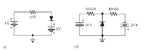
hope it helps:I need some help.
determine the voltage across each diode assuming practical diode model.
how would I go about it? thanks!