Continue to Site

Welcome to EDAboard.com

Welcome to our site! EDAboard.com is an international Electronics Discussion Forum focused on EDA software, circuits, schematics, books, theory, papers, asic, pld, 8051, DSP, Network, RF, Analog Design, PCB, Service Manuals... and a whole lot more! To participate you need to register. Registration is free. Click here to register now.

Dimming AC loads using triac and microcontroller

Status
Not open for further replies.

raghurocks

Member level 1
Joined
Jul 3, 2012
Messages
33
Helped
2
Reputation
4
Reaction score
0
Trophy points
1,286
Location
India,Gujarat
Activity points
1,568
Hai Everyone,
I have been working under I have been working under dimming of ac loads using the microcontroller .
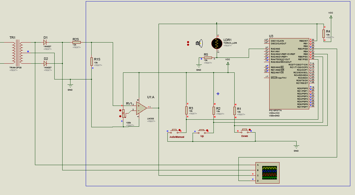
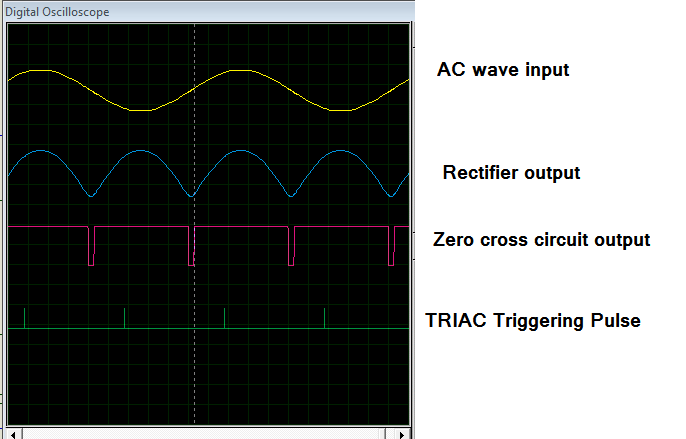
The concept I am using is the based upon the basic operation of the triac, as once the gate of the triac gets the trigger it will be on for next zero cross
so for this I have taken a basic zero cross detection circuit where it detect the every zero crossing so this output is given to the one of the interrupt pin of the microcontroller and I have done the coding like after it detects the zero cross that is from the external interrupt it waits for some time (delay time) which indulge in the delay angle which inturn changes the conduction angle of the triac and so the output voltage so this delay time can be varied to change the brightness as the rms output voltage will be varied I have change this delay time or the delay angle into 16 levels where the brightness is also varied in 16 levels so far I think I am clear........... Any suggestions in the concept are appreciated .......

Basing on this I have written the interrupt routine to give some amount of delay basing on the level (this level is determined from the input it get from the port p1 of the microcontroller where I used 4 switches connected to the p1.0,p1.1,p1.2,p1.3 that is if all the switches are on then the level will be 1111 that is 0x0F so for this there will be different delay time or delay angle like wise the levels will be from 0x00 to 0x0F which inturn should vary the brightness) I think I am clear with the input how the microcontroller gets 16 different levels of input and how it it will vary different levels of delay angle........ Any doubt can be expressed

Coming to the triac output section it consists of the basic application circuit from the application note with a snubber network .

The tricky part included in this is I am getting the output exactly as I desire in the Proteus emulator but I don't know why I am not getting the desired output in the hardware

Any explanations or suggestions or clarification are appreciated
Thanks in advance
Raghu
 

1. Publish hardware / circuit diagram
2. Publish code.
3. Which microcontroller?
4. which compiler? etc
 

final_tahmid.jpg
The circuit remains same the only modification is the output of zero crossing is given to the interrupt pin not the p2.1
code:
Code:
#include<reg51.h>

// LED Pin
sbit LED = P2^0;		   // Pin P2.0 is named as LED

//Function declarations
void cct_init(void);
void InitINT0(void);
void delay(int );

// Main function
void main(void)
{
   cct_init();   	// Make all ports zero
   InitINT0();      // Intialize INT0 interrupts
 
   while(1)
   {}
}

// Init CCT function
void cct_init(void)
{
	P0 = 0x00;    // Make all pins zero
	P1 = 0x00;    // Make all pins zero
	P2 = 0x00;    // Make all pins zero
	P3 = 0x00;    // Make P3.2 (INT0) pin high only
}

// External INT0 pin interrupt init function
void InitINT0(void)
{
	IT0 = 1;      //Edge triggered interrupt mode (Neg Edge)
	EX0 = 1;      //Enable external interrupt INT0
	EA  = 1;      //Enable global interrupts
}

// INT0 ISR
void external0_isr(void) interrupt 0     						//zero detection interrupt routine
{
	//LED = ~LED;   // Toggle LED pin
	if(P1==0x00)
	{	
		LED=0;
	}
	else if(P1==0x01)
	{
		LED=1;
		delay(20);//trigger immediately after the zero detection
		LED=0;
	}
	else if(P1==0x02)
	{
		LED=0; //delay angle before which the triac triggers
		delay(50);
		LED=1;
		delay(20);//this delay is for the trigger pulse for the triac ~100us
		LED=0;
	}
	else if(P1==0x03)
	{
		LED=0; //delay angle before which the triac triggers
		delay(100);
		LED=1;
		delay(20);//this delay is for the trigger pulse for the triac ~100us
		LED=0;
	}
	else if(P1==0x04)
	{
		LED=0; //delay angle before which the triac triggers
		delay(150);
		LED=1;
		delay(20);//this delay is for the trigger pulse for the triac ~100us
		LED=0;
	}
	
	else if(P1==0x05)
	{
		LED=0; //delay angle before which the triac triggers
		delay(200);
		LED=1;
		delay(20);//this delay is for the trigger pulse for the triac ~100us
		LED=0;
	}
	else if(P1==0x06)
	{
		LED=0; //delay angle before which the triac triggers
		delay(250);
		LED=1;
		delay(20);//this delay is for the trigger pulse for the triac ~100us
		LED=0;
	}
	else if(P1==0x07)
	{
		LED=0; //delay angle before which the triac triggers
		delay(300);
		LED=1;
		delay(20);//this delay is for the trigger pulse for the triac ~100us
		LED=0;
	}
	else if(P1==0x08)
	{
		LED=0; //delay angle before which the triac triggers
		delay(350);
		LED=1;
		delay(20);//this delay is for the trigger pulse for the triac ~100us
		LED=0;
	}
	else if(P1==0x09)
	{
		LED=0; //delay angle before which the triac triggers
		delay(400);
		LED=1;
		delay(20);//this delay is for the trigger pulse for the triac ~100us
		LED=0;
	}
	else if(P1==0x0A)
	{
		LED=0; //delay angle before which the triac triggers
		delay(450);
		LED=1;
		delay(20);//this delay is for the trigger pulse for the triac ~100us
		LED=0;
	}
	else if(P1==0x0B)
	{
		LED=0; //delay angle before which the triac triggers
		delay(500);
		LED=1;
		delay(20);//this delay is for the trigger pulse for the triac ~100us
		LED=0;
	}
	else if(P1==0x0C)
	{
		LED=0; //delay angle before which the triac triggers
		delay(510);
		LED=1;
		delay(20);//this delay is for the trigger pulse for the triac ~100us
		LED=0;
	}
	else if(P1==0x0D)
	{
		LED=0; //delay angle before which the triac triggers
		delay(520);
		LED=1;
		delay(20);//this delay is for the trigger pulse for the triac ~100us
		LED=0;
	}
	else if(P1==0x0E)
	{
		LED=0; //delay angle before which the triac triggers
		delay(530);
		LED=1;
		delay(20);//this delay is for the trigger pulse for the triac ~100us
		LED=0;
	}
	else if(P1==0x0F)
	{
		LED=0; //delay angle before which the triac triggers
		delay(540);//the maximum for 50hz signal
		LED=1;
		delay(20);//this delay is for the trigger pulse for the triac ~100us
		LED=0;
	}
}
void delay(int n)
{
	int i;
	for(i=0;i<=n;i++);
}
Microcontroller at89c51
compiler: keil uvision
 

The tricky part included in this is I am getting the output exactly as I desire in the Proteus emulator but I don't know why I am not getting the desired output in the hardware


Exactly at which place you're finding problem with your hardware ?

upto which section circuit is working?

and what output at where makes the problem
& what output at that place you're getting in proteus ?
 

Hi Jigar,
Exactly at which place you're finding problem with your hardware ?

upto which section circuit is working?

and what output at where makes the problem
& what output at that place you're getting in proteus ?
I don't know where is the wrong in the hardware . I think the triac trigger circuit is fine as it is typical application circuit I think my microcontroller is not triggering .
The output I got in the proteus is that if I change the levels of input the output voltage is changing
but in my hardware my lamp is on for all levels irrespective of the input
 

What o/p you're getting at the o/p stage of Zero Crossing Detector in your hardware?
I mean what is the specification of that pulse, check it on oscilloscope if possible.
it should be almost 5V when it is high & almost 0V when it is low.

& if you've doubt that your controller is not triggering then,
In programming try to use +ve edge trigger interrupt & make a simple demo program to just detect that +ve edge trigger interrupt and to respond it by LED blinking on other pin of controller.

This is just to find whether you're getting an interrupt or not.
once you get that you're getting an interrupt or not then you can confirm that the i/p circuit is 100% working & so you can get a perfect location of the problem.

in short divide your circuit in 3 steps.

in first just check your i/p circuit (upto the interrupt pin of controller),
in second by feeding an interrupt check your o/p to know whether the program is working or not &
in third try to debug your o/p circuit.

through this way you can limit your circuitry task and can get the perfect location of the problem.

NOTE: during implemented each step the rest part of the circuit should be isolated/disconnected.

All the best
 
Hi Jigar,
in first just check your i/p circuit (upto the interrupt pin of controller),
in second by feeding an interrupt check your o/p to know whether the program is working or not &
in third try to debug your o/p circuit.

Actually this is what I have done,
1.In the first step I have checked for the zero crossing detecting circuit i.e, it is 5v trigger which is coming like a spike
2.In the second step to know whether my uC is triggering or not I have first written a pwm program where we can see dimming of the dc loads when I remove the signal from zero detection circuit to the uC the led is in off state when I give the trigger and vary the levels the dimming of the dc loads is done so by this I came to know I have done my getting the triggering part is ok.
3.In the third step I changed code and concept I have explained I gave the program in that way then nothing is happening are you sure my concept is right which I had explained it Earlier that is "varying the delay angle before which my triac triggered I can change the brightness of the ac loads is controlled"
So only way I may go wrong is that either I may go wrong in the triac circuit or I may be wrong in the coding to my uC in case of triac triggering, which I am unable to know

And actually I have tried for delay circuits in both the ways one way I have given it in the above mentioned code and the other is using timers the unlucky part is that both are not working.
Thanks in advance,
M.Raghu.
 

HI Jestin
Can you post the code for reference as I don't know anything about the pic microcontroller coding
 

Code:
#include <pic.h>                                              //triac light dimmer   
#define _XTAL_FREQ 20000000

#define TRIAC1 RB3        
#define UP  RB7 
#define DWN RB6 

#define MAX_TIME 3500
#define MIN_TIME 1

int k=0,dly=0;

void interrupt isr()
{
///////////////////////////////////// 
if(INTF)
{
INTF=0; 
while(!RB0); 
dly=k;
while(dly--); 
TRIAC1=1;
#asm
nop;nop;nop;nop;nop;nop;
nop;nop;nop;nop;nop;nop; 
nop;nop;nop;nop;nop;nop;
#endasm
TRIAC1=0; 
}
}
/////////////// MAIN //////////////////////
void main()
{
 TRISD=0x0; TRISB=0xF1;
    
   k=300;
 INTE=1; INTEDG=1;    PEIE=1;GIE=1;

while(1)
{
if(!UP)
{
__delay_ms(100);  
if(!UP)
{
  if(k>=MAX_TIME) k=MAX_TIME; k++;  
 dly=k;
}   
} 
 else if(!DWN)
{
__delay_ms(100);
if(!DWN)
{
   if(k<=MIN_TIME) k=MIN_TIME; k--;   
 dly=k;
}
} 
 }
}
/////////////////////////////////////////////////
 

Hi Jigar,


So only way I may go wrong is that either I may go wrong in the triac circuit or I may be wrong in the coding to my uC in case of triac triggering, which I am unable to know

That's the good news that you get the nearer location of the problem.

Now to know whether the program is right or not, remove the o/p circuit from P2.0
connect the LED with 1k resistor to P2.0
Don't change the program, keep it as it is in your earlier comment and try it along with your i/p circuit & MCU.

I've not checked your code in detail but I think this will make you sure whether your code is working or not.

& even after this If you still not get the area of the problem then upload your proteus files.
may anyone on edaboard (including me) can have the solution from the files.
 

Hi Jigar,
Thanks for your reply but I have small doubt is that here I am giving the trigger for around 0.1ms so if I connect LED to the output pin is it possible that I can see the blinking ?.

And regarding the delay as for at89c51 microcontroller has no default delay function I had written a delay function using a for loop and later I tried using the timer there is a difference between them so my doubt is it required to write the delay function using a timer interrupt .

And another doubt is that in the previous comments I have given my concept like giving the trigger to the gate of the triac at different times of the ac cycle but now by interchanging the pins going to the optocoupler I tried another concept like Pwm just varying the duty cycle I have written 10 levels the thing is that instead of dimming it is blinking and later I tried the same concept of Pwm in atmega it is working dimming is happening. Is at89c51 is not suitable for dimming using the pwm

Thanks in advance,
Raghu.M.
 
Last edited:

Status
Not open for further replies.

Similar threads

Part and Inventory Search

Welcome to EDABoard.com

Sponsor

Back
Top