Continue to Site

Welcome to EDAboard.com

Welcome to our site! EDAboard.com is an international Electronics Discussion Forum focused on EDA software, circuits, schematics, books, theory, papers, asic, pld, 8051, DSP, Network, RF, Analog Design, PCB, Service Manuals... and a whole lot more! To participate you need to register. Registration is free. Click here to register now.

Digital Gages for Tractor

Status
Not open for further replies.

IMSlo

Newbie level 6
Joined
Oct 1, 2006
Messages
13
Helped
0
Reputation
0
Reaction score
0
Trophy points
1,281
Activity points
1,499
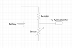
I am toying around with building pic based digital gages for my tractor. The gages would be fuel, temperature, oil pressure and battery. I need some help understanding how a couple of these could be done. The fuel is very straight forward. It has a variable resistor/rheostat operated by a float in the tank. You simply send a voltage to it and measure how much you get back. The oil pressure gage is now an idiot light. How would you use a pic in this situation? If there is pressure the sending unit is insulated from the engine. If no pressure the unit is in electrical contact with the engine. There is only a single wire going to this unit. Worse yet is the temperature sensor. It must be a variable resistor. I can understand how the hand of a gage could move up or down depending upon the resistance in the circuit. There is only one wire going to this sensor. How do you measure resistance to ground with a pic? Any help would be appreciated.
 

The temp sensor works in the same (general) manner as the fuel sensor. You measure the output voltage and calculate the temperature.
All the analog gauges are, basically, voltmeters - the higher the voltage, the more the needle moves.


As for the oil pressure mechanism, depending on the physical design of the tractor, you may be able to find a suitable digital pressure sensor somewhere and mount it in place of the ON/OFF switch used to drive the oil lamp. Then you could measure the Oil pressure the same way as the rest of the signals.
 

There is no output voltage from the sensor. It is connected through the metal of the tractor to the negative side of the battery.

The analog gage has a positive connection to the battery on one side and is connected to the negative side of the battery through the sensor. There is only one wire going to the sensor which completes the circuit through the analog gage.

I don't know how get this circuit through the pic.
 

I've been toying with the idea of doing the same, but as a data logging "black box" type device. Something that can log things like fuel pressure, oil temp, coolant temp, manifold pressure, etc...
 

There is no output voltage from the sensor. It is connected through the metal of the tractor to the negative side of the battery.

The analog gage has a positive connection to the battery on one side and is connected to the negative side of the battery through the sensor. There is only one wire going to the sensor which completes the circuit through the analog gage.

I don't know how get this circuit through the pic.

Do you know anything about basic electronics? Such as the Ohm's law?
 

I'm far from being an expert in electronics but I do know about Ohm's law.
 

Ok, so if you have a variable resistor and a voltmeter - would you know how to hook it all up so that the voltmeter reads the voltage drop on the variable resistor (ie: measure the voltage output of a sensor)?
 

I have used a pot for adc pwm on the pic to control the speed on a small DC motor. I hooked one side to +5v the other side to 0v and hooked the middle to a pic pin. I suppose if I was trying to read the voltage with a voltmeter I would hook the positive lead to the to the middle lead of the pot and the negative lead to the 0V rail.
 

I glad I passed the test on how to read voltage on a pot but I can't relate this to a one lead sensor.

If someone could give me a simple schematic on how to connect this sensor to a pic I would appreciate it.
 

You'd just need to calculate the value of the sensor so that the output voltage doesn't go above 5V so you don't kill the MCU.
 

Attachments

  • sensor.png
    sensor.png
    24 KB · Views: 36

Thanks for the help jumper2high. That looks like a voltage divider.

I'm still going to have to think about it but I think I can get it now.
 

Status
Not open for further replies.

Part and Inventory Search

Welcome to EDABoard.com

Sponsor

Back
Top