Continue to Site

Welcome to EDAboard.com

Welcome to our site! EDAboard.com is an international Electronics Discussion Forum focused on EDA software, circuits, schematics, books, theory, papers, asic, pld, 8051, DSP, Network, RF, Analog Design, PCB, Service Manuals... and a whole lot more! To participate you need to register. Registration is free. Click here to register now.

differential to single ended circuit

Status
Not open for further replies.

bigredram87

Newbie level 2
Newbie level 2
Joined
Dec 10, 2014
Messages
2
Helped
0
Reputation
0
Reaction score
0
Trophy points
1
Visit site
Activity points
17
I have a very small 3 phase motor that I need to measure the voltage from Phase A to Phase B. Now I can easily take my DVM on AC and measure this voltage, however I need this in a permanent fixture with Panel Meters. I already have the panel meters mounted and wired but the problem is they only accept single ended inputs. Now I need to design a circuit that will take my Max 100V Phase to Phase voltage and output it as a single ended +/- signal that my panel meter can understand. Any Help would be much appreciated
 

Signal transformer rated for high voltage transient insulation (>10kV) may be simplest solution.

Also a remote differential Amp could be used powered by the DMM. Consider 100:1 gain reduction with low current. and calibrate it. DC to sensor and AC couple to meter.


Make sure the divider can handle worst case line impulse voltages ( 3kV to 15kV) ( or include a transient filter down to ground with low current to ground then take the differential. Put the bridge near the motor and run low voltage to the DMM.

Keep in mind Star Ratio dividers ensure low voltage if 1 phase breaker is opened , whereas Delta measurements would have an excessive common mode voltage. COnsider differential and CM chokes in the divider to reduce EMI.


But after thinking about EMI problems with single ended input, I think a 100:1 HV rated signal transformer is best for you with CM choke and plastic film cap on meter using shielded twisted pair and Transzorb input protection depending on line length and a series current limiting resistor in case of a fault.. Who knows how much EMI you have around you?
 

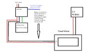
Could you explain the differential amp idea a little further. The thing I was not real clear on is this is a extremely small Pc controlled 3 phase motor smaller than your fist so I don't think I am going to need to use typical protection circuits I have attached a very bad diagram just to make it a little more clear.
 

You either need to create a -V/2 ref via separate R to inject V+/2 output offset ( unity gain) for a single supply 5V Quad Op Amp ( rail to rail) and AC couple output to AC meter.
Or you need +/-5V supply. ( -5V Charge pump )

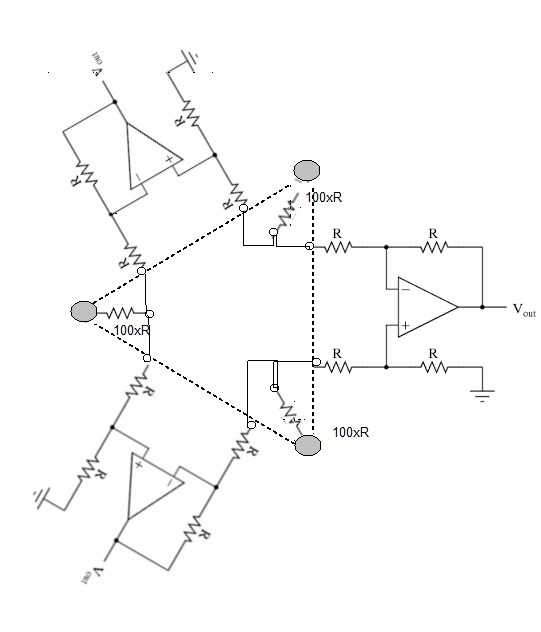
This is what I had in mind for a 3 phase 100Vac to 1Vac differential to single ended grounded DPM.

Add feedback noise caps and series DC blocking caps if necessary. ( Usually is)

Since your DPM probably only measures + peaks with a diode and converts to DC, you may want to limit BW to 100Hz and forget the bipolar supply and rectify both peaks with diode feedback as well or clip the the negative peaks with a filtered single 5V supply. More details to simplify and resolve Ground vs Neutral issues and EMI required.. or not. But can be implemented with R DIPs and Quad OA DIP in 3 sockets.
9235877800_1418314866.png

Otherwise use these ~10:1 transformers 1" cube rated for 120/240V $10 at Digikey and use another 10:1 R divider to DPM and adjust R for exact 100:1 overall.

http://www.hammondmfg.com/pdf/5c0011-12.pdf
 

Status
Not open for further replies.

Part and Inventory Search

Welcome to EDABoard.com

Sponsor

Back
Top