Continue to Site

Welcome to EDAboard.com

Welcome to our site! EDAboard.com is an international Electronics Discussion Forum focused on EDA software, circuits, schematics, books, theory, papers, asic, pld, 8051, DSP, Network, RF, Analog Design, PCB, Service Manuals... and a whole lot more! To participate you need to register. Registration is free. Click here to register now.

differential amplifier circuit doubt

Status
Not open for further replies.

4tuty

Member level 3
Joined
Mar 27, 2012
Messages
56
Helped
0
Reputation
0
Reaction score
0
Trophy points
1,286
Activity points
1,723
I want to measure differential voltages from two photodarlington(PD)

1. reference fiber
2. sensing fiber connected single IRled to both PD via fiber optic.

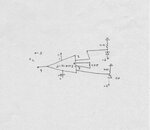
I used LM328 as differential amplifier (Gain 2.2). I am not getting correct output View attachment nre.pdf. Is there any mistake in my circuit or shall i go for singly supply differential amplifier IC like INA 132.

Please find the attachments for my circuit
 

Hi,

You write "LM328". I assume you mean LM358.

I don't think the LED driving circuit makes sense.

What exactely do you expect? How do you measure it? And what results do you see?

Klaus
 

I don't think the LED driving circuit makes sense.
It looks like a valid constant current circuit (with some temperature dependency).
 

Hi

It looks like a valid constant current circuit (with some temperature dependency).
This is what I mean.
I assume the current with this current source circuit will drift more with temperature than with a simple resistor.
Because the voltage comes from a 7805.

Klaus
 

Thanks to every one for the response

@KlausST
(LM358 yes)edited in thread. can you suggest me better constant source circuit. because, i am using 9Volt battery to get constant 5 volt i used 7805 regulator or any alternative way to get 5volt?. The circuit was given by @crutschow in this thread and worked like a charm.

I found that it needs buffer so i change the circuit to instrumentation amplifier 1.jpeg and i get to see results but the changes are in milivolts (3rd digit in multimeter). How to improve this?

@crutschow it is in inline a pdf
 

Hi,

Constant current source:
I think there is no need for it.
The supply voltage is constant and the LED forward voltage is constant and the resustor us constant (all within their drifts).
Therefore the current is constant, too.

V_BE of Q2 sets the current (in combination with the current sensing resistor). It is around 560mV and drift with about -2mV/°C.
--> A temperature change of 10°C leads to 20mV drift this is 3.6%.
I assume this drift is no benefit compared to the "single resistor" solution.

The given circuit makes sense when you don't have a regulated supply voltage... like the battery alone...

****
but the changes are in milivolts
You still don't give any information about what you want to achieve with your circuit.
I don't know where in the circuit those "millivolts" are...and you don't give any specifications.

Therefore it's impossible to help.

Klaus
 

Status
Not open for further replies.

Similar threads

Part and Inventory Search

Welcome to EDABoard.com

Sponsor

Back
Top