Continue to Site

Welcome to EDAboard.com

Welcome to our site! EDAboard.com is an international Electronics Discussion Forum focused on EDA software, circuits, schematics, books, theory, papers, asic, pld, 8051, DSP, Network, RF, Analog Design, PCB, Service Manuals... and a whole lot more! To participate you need to register. Registration is free. Click here to register now.

Difference between MOScap and MOS varactor

Status
Not open for further replies.

eli631

Newbie level 4
Joined
Nov 18, 2010
Messages
5
Helped
2
Reputation
4
Reaction score
3
Trophy points
1,283
Activity points
1,325
Hi all;
I need some information about variable capacitors in CMOS.
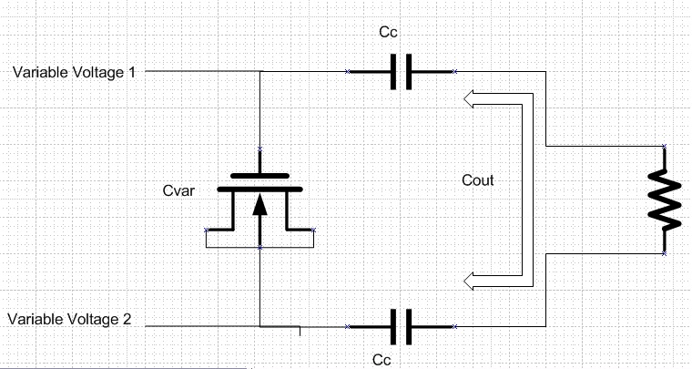
As I know, NMOScap is a normal NMOS built in Pwell, source and drain connected together and body is grounded. also. N-varactor is NMOS built in Nwell, so drain, source and body are connected together. i need to know whether we can use a varaactor in 0.18um CMOS Tech or not, i. e. do we access to the body of a transistor to bias?
is it needed to use a series of codes to build a varactor in Hspice or just needed this single line?
Mvar a gate a a nch L="L" , W="W" : Varactor
Mvar a gate a 0 nch L="L" , W="W" : MOScap

another question:
what does the Varactor/MOScap capacitance mean? is it just the capacitance seen from gate terminal or capacitance between gate and drain/source/(body) terminals?

thanks in advanced as wait for replies :-D
 

A MOS varactor is a MOScap, but you might lay it out with
different priorities - wanting high Q (low rG), trying extra
hard to isolate the bottom plate from the substrate (a
decoupling MOScap, you'd probably just tie it down more
stiffly to psub/GND). You might see a different (like intrinsic)
species used if available, depending on where you want the
C-V curve to pivot in the common-mode range. You might
see thicker oxides used if you want a wide control voltage
range or to accommodate larger signal swings with less
distortion.

You would probably prefer to (RF-) ground the body, source
and drain and only "see" the gate. Otherwise you'd have a lot
of charge partitioning and more nonlinear capacitances in the
mix.
 

Dear dick-freebird
I appreciate for your reply. as you mentioned MOS varactor is a kind of MOScap but there is a structural difference between MOScap and MOS varactor in the attached file and they have different C-V curve,(page 4).
1- I'm going to use such variable capacitor as the variable impedance connected to an antenna, so i need to know which one has a larger range of capacitance variation in the smaller voltage range. what do you suggest?
2- also, I can just change the transistor size(W,L) not the thickness of oxide. as i understood from your notes, since there is no access to oxide thickness,i can not change the control voltage range.

please give me some advises to choose the best.
Best Regards;
Eli
 

Attachments

  • LC_Oscillator-Varactor.pdf
    421 KB · Views: 996
... another question:
what does the Varactor/MOScap capacitance mean? is it just the capacitance seen from gate terminal or capacitance between gate and drain/source/(body) terminals?

The latter. Pls. find below a PDF with several MOScap (=MOSvaractor) structures with a varicap ratio of ≈ 1:4 over their control voltage range. The values given are for a 0.18µm CMOS process (with two different oxide thicknesses for 1.8V and 3.3V MOSFETs).

View attachment MOSCAP_voltage_dependency.pdf
 
Dear Erikl;
I thank you very much for the useful attached document. it helped me a lot. I now know which one is better for the given application. i just have another question. i hope it will be the last!
I am going to use the MOScap in a structure that its schematic is attached. the voltage of both terminals of MOScap(G,S/D/B) is changed. certainly, the capacitance is not just Cgate, because the capacitance of MOScap depends on Vgate and Vsource not just Vgs (gate - source voltage)! so all charts in documents shift up or down if dc voltage is applied to S/D/B terminals and also a capacitance is seen in S/D/B terminals which is different from Cgate. although, i think that these 2 capacitances should be the same, they are not the same in my simulations. what's your opinion?! am i right?!do you think that the capacitance of D/S/B terminals are as important as Cgate?!

Best Regards;
Eli


... do you think that the capacitance of D/S/B terminals are as important as Cgate?!

If you got the single capacitances (Cgs, Cgd, Cgb) from a preLayout analysis: these caps are derived from the (MOSFET) model, and are calculated including their voltage dependency.

If you got them after a postLayout analysis, then possibly additional parasitic caps are included, which may -- or may not -- have been calculated including their voltage dependencies, depending on your extractor setUp.

In any case, all these caps have to be added in order to get the real capacitance value.

The easiest way to get the total capacitance between the 2 cap nodes is to inject a (unit) current source between the 2 nodes, then run an AC analysis and plot the cap's impedance (= cap voltage, because Ω≘V (or MΩ≘MV) for unit current = 1A) vs. frequency.
 
Thank you Dear Erikl for all your guidance. it helped me more than you can guess!
 

Status
Not open for further replies.

Part and Inventory Search

Welcome to EDABoard.com

Sponsor

Back
Top