Continue to Site

Welcome to EDAboard.com

Welcome to our site! EDAboard.com is an international Electronics Discussion Forum focused on EDA software, circuits, schematics, books, theory, papers, asic, pld, 8051, DSP, Network, RF, Analog Design, PCB, Service Manuals... and a whole lot more! To participate you need to register. Registration is free. Click here to register now.

Detector probe max input voltage

neazoi

Advanced Member level 6
Joined
Jan 5, 2008
Messages
4,122
Helped
13
Reputation
26
Reaction score
15
Trophy points
1,318
Location
Greece
Activity points
36,951
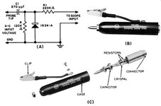
Hi, I have built this detector probe (RCA design) http://qrp.gr/dprobe/ to be able to align filters with a low bandwidth scope or measure transmitter power when probe/transmitter is loaded to 50 ohms.
The only change I did, was to use the 1N58A diode instead.

I want to determine, what is the maximum voltage I can put in the probe tip without damaging the diode (and hence the maximum RF power into a 50 ohms load)
 

Attachments

  • rider_test_probes_7-9.jpg
    rider_test_probes_7-9.jpg
    35.4 KB · Views: 74
  • 1N58A.PDF
    49.8 KB · Views: 60
It depends on the frequency - treat Xc of the capacitor as the top resistor in a potential divider and 120K in parallel with Xc of the diode as the bottom resistor. As a guess, the diode will be about 5pF. Then multiply the PIV (100V) of the diode by the ratio.

Note that it is a rectifier so expect a DC output. A scope will show half cycles but a voltmeter will suffice to measure power.

Brian.
 

    neazoi

    Points: 2
    Helpful Answer Positive Rating
It depends on the frequency - treat Xc of the capacitor as the top resistor in a potential divider and 120K in parallel with Xc of the diode as the bottom resistor. As a guess, the diode will be about 5pF. Then multiply the PIV (100V) of the diode by the ratio.

Note that it is a rectifier so expect a DC output. A scope will show half cycles but a voltmeter will suffice to measure power.

Brian.
Oh! So it will be more than 100v peak, or more than 200vpp? I have not realized this as an input potential divider!
 
The diode will clamp in the forward direction, holding the voltage to about 0.5V. In the reverse direction the maximum the diode can take is 100V and that will be at the peak of each cycle. Allowing for some drop in the capacitor, which if frequency dependent you could apply a little over 100V peak.

So, ignoring any loading effect the probe has on the signal itself and assuming a sinusoidal waveform, +100V to -100V is 200V p-p or about 140V RMS. Across a 50 Ohm load you could measure up to about 400W.

Brian.
 

    neazoi

    Points: 2
    Helpful Answer Positive Rating
The diode will clamp in the forward direction, holding the voltage to about 0.5V. In the reverse direction the maximum the diode can take is 100V and that will be at the peak of each cycle. Allowing for some drop in the capacitor, which if frequency dependent you could apply a little over 100V peak.

So, ignoring any loading effect the probe has on the signal itself and assuming a sinusoidal waveform, +100V to -100V is 200V p-p or about 140V RMS. Across a 50 Ohm load you could measure up to about 400W.

Brian.
Thank you Brian!
I was thinking about it in a more simplistic way, which in fact agrees with your more elaborate explanations. That is, a diode with max peak reverse voltage of 100v, connected in shunt in reverse, will tolerate a peak of -100V. The positive peak (of a sine) will be +100V, but this one is not clamped from the diode to the ground, so it passes on to the output of the envelope detector. Thus a total of 200Vpp, or double the reverse peak voltage of the diode.

Now, this can be 200Vpp unloaded, 200Vpp loaded to 50R, 200Vpp loaded to other loads (eg 600R etc). The load does not matter for the diode, all it matters is to keep it's maximum reverse voltage within limits in this shunt configuration. I hope I get this right.
--- Updated ---

The diode will clamp in the forward direction, holding the voltage to about 0.5V. In the reverse direction the maximum the diode can take is 100V and that will be at the peak of each cycle. Allowing for some drop in the capacitor, which if frequency dependent you could apply a little over 100V peak.

So, ignoring any loading effect the probe has on the signal itself and assuming a sinusoidal waveform, +100V to -100V is 200V p-p or about 140V RMS. Across a 50 Ohm load you could measure up to about 400W.

Brian.
200Vpp is 100W at 50 ohms, I guess 400W is a typo.
 
Last edited:
My apologies, 200v p-p is 70.7V RMS so into 50 Ohms it would be 99.97W.
Excuse my brain, it's getting old!

Brian.
 

    neazoi

    Points: 2
    Helpful Answer Positive Rating
My apologies, 200v p-p is 70.7V RMS so into 50 Ohms it would be 99.97W.
Excuse my brain, it's getting old!

Brian.
Dear Brian,
Here is an explanation from another fellow from the internet, which suggests that the max input voltage of the probe cannot be more than half the max reverse voltage of the diode. If I understand it correctly this means that the input signal can be in fact a max of 50Vpp for a diode with max reverse voltage of 100Vpeak, if I get this right?

What do you think?

"In the circuit shown in the link above, assuming a sine wave input, the operation is as follows. The diode will conduct when the input signal is negative going. This will charge the input capacitor (ignoring the diodes forward voltage drop) to V peak. With the junction of the capacitor and the cathode being positive with respect to the probe's input. During the input's positive half cycle, this stored DC will add to the input voltage. Causing the diode's cathode to rise to 2 x V peak. The probes DC output now comprises a sinewave where the negative peak is now referenced to ground. In analogue TV circuit terms, this is called a DC restorer. The 220KΩ resistor, plus the input capacitance of the oscilloscope and connecting cable forms a low pass filter. Which removes the RF ripple and gives a DC output equal to the the input's peak, less the diode's forward drop. So both the input capacitor and the diode's voltage rating must be at least equal to the maximum peak to peak input voltage. If you wish to see the circuit in action, make a diode probe with a larger input capacitor. Say a 0.1uF, non electrolytic, feed it from an audio generator. And observe the waveforms on your oscilloscope, (set to DC input)."
 
100 Vpp = 35 Veff is the correct answer, assuming there's no voltage divider effect.
 

    neazoi

    Points: 2
    Helpful Answer Positive Rating

LaTeX Commands Quick-Menu:

Part and Inventory Search

Welcome to EDABoard.com

Sponsor

Back
Top