Continue to Site

Welcome to EDAboard.com

Welcome to our site! EDAboard.com is an international Electronics Discussion Forum focused on EDA software, circuits, schematics, books, theory, papers, asic, pld, 8051, DSP, Network, RF, Analog Design, PCB, Service Manuals... and a whole lot more! To participate you need to register. Registration is free. Click here to register now.

[SOLVED] Designing Power Supply

Status
Not open for further replies.

sinCERA

Junior Member level 1
Joined
Feb 25, 2013
Messages
15
Helped
0
Reputation
2
Reaction score
1
Trophy points
1,283
Location
Philippines
Activity points
1,375
Hi sirs,

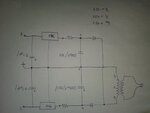
We're making power supply for our ampli and equalizer project. And I've decided to use only one transformer (IN:220Vac; OUT:16Vac center-tapped/6 Amperes), 6A05 bridge rect., and LM7815 and LM7915. My amplifier requires 45Vdc/6A and the equalizer needs ±15Vdc/1A (for the ICs).
Btw, here's my design and I don't know if the component values or the design itself is correct.
IMG02269-20130225-1345.jpg
Please help me guys. Thanks in advance. :)
 
Last edited:

you've got problems as the "45V" is not 45V with respect to the grounded centre tap, it is only half this, you need seperate windings to give you your +/- 15V supplies then you can tie the 0V of the +/- 15 to the 0V of the 45V o/p...
 
you've got problems as the "45V" is not 45V with respect to the grounded centre tap, it is only half this, you need seperate windings to give you your +/- 15V supplies then you can tie the 0V of the +/- 15 to the 0V of the 45V o/p...
I'm sorry but I can't really picture out what you're trying to say. Especially the "separate windings...". Do you mean I have to use two bRidges?
Please understand I'm just a newbie in electronics. But I'll really appreciate you're help on this:)
 

I'm sorry but I can't really picture out what you're trying to say. Especially the "separate windings...". Do you mean I have to use two bRidges?
Please understand I'm just a newbie in electronics. But I'll really appreciate you're help on this:)


1.If you want 15 V output from LM7815 input voltage of the regulator must be in 17.5 V to 30 V. This condition same for LM7915 input voltage - 30 V to - 17.5 V. ## Refer datasheet
2. You need separate windings for 45 V.
 
1.If you want 15 V output from LM7815 input voltage of the regulator must be in 17.5 V to 30 V. This condition same for LM7915 input voltage - 30 V to - 17.5 V. ## Refer datasheet
2. You need separate windings for 45 V.
I see. Could you please give me a schematic for this? :)

Is it ok if I input 6 Amperes 16Vdc to my LM7815 and 7915? I didn't find the max input current rating for the LM79xx and 78xx on their datasheets. What will happen to the regulators if I do this?
 

LM78xx series regulator 1 A max. output current. LM79xx is 1.5 A max. output current. Read the datasheet properly..

Search in GOOGLE" lm7805 circuit diagram"
 
Last edited:

i already know their output currents. my question is that if it's ok if I input 6 amperes to these regulators. what will happen to them if i do this? :)

Should the input currents for these regulators be the same as their outputs? :)
 

The 78xx and 79xx series regulators are linear regulators. This means that the input current is same as the output current.
You do not input current into a load. The current is drawn by the load.
If the load after the regulator draws 6A, the regulator will burn since it is drawing current that is much larger than the rated max current.
Your circuit requires ±15V at 1A, this is quite close to the rated current for the regulators and you will need heat sinks. You can still use your circuit to generate this.

As mentioned before by others, the 45V that you have is not wrt the ground node. If you measure that voltage wrt the ground node you will see only ±16√2 Volts.
If you want 45V, you can go for a transformer with another secondary winding which will give this voltage.

You are consuming a lot of current and using linear regulators would be very inefficient.
 
Thank you so much nitishn5. I very much appreciate your help. :)
 

Thank you so much nitishn5. I very much appreciate your help. :)


You don't worry about input current of the regulator . But the input current must be higher then output current. If you draw the Load current Max 1 A the regulator generate heat. So you must be provide heat sink.
 

IMG02271-20130227-1224.jpg

How about this one guys. I used voltage doubler here. Can I get now the required voltages (45V,+15V, -15V)?

Need your opinions 'bout this..
:)
 

Attachments

  • IMG02271-20130227-1224.jpg
    IMG02271-20130227-1224.jpg
    383.1 KB · Views: 85

Sorry, not quite there yet, this one has problems, including too much voltage feeding the regulators (I think they are 40V max in).

What you need is a single high current winding to get the 45V you want (via a full bridge rectifier), then a high voltage regulator to get the +15 you require (running off the 45V)

Then a circuit to convert the +15 to -15V (with respect to the 0V of the +45 & +15), thus giving you all three outputs.

- - - Updated - - -

OK, here is a workable solution for you using your exiting centre tapped transformer...
 

Attachments

  • PSU solution.PDF
    39.9 KB · Views: 103
Sorry, not quite there yet, this one has problems, including too much voltage feeding the regulators (I think they are 40V max in).

What you need is a single high current winding to get the 45V you want (via a full bridge rectifier), then a high voltage regulator to get the +15 you require (running off the 45V)

Then a circuit to convert the +15 to -15V (with respect to the 0V of the +45 & +15), thus giving you all three outputs.

- - - Updated - - -

OK, here is a workable solution for you using your exiting centre tapped transformer...


Thank you Orson Cart!
:)
 
Sorry, not quite there yet, this one has problems, including too much voltage feeding the regulators (I think they are 40V max in).

What you need is a single high current winding to get the 45V you want (via a full bridge rectifier), then a high voltage regulator to get the +15 you require (running off the 45V)

Then a circuit to convert the +15 to -15V (with respect to the 0V of the +45 & +15), thus giving you all three outputs.

- - - Updated - - -

OK, here is a workable solution for you using your exiting centre tapped transformer...

By the way, what's wrong with this schematic you first gave me?
This looks fine.
 

Status
Not open for further replies.

Similar threads

Part and Inventory Search

Welcome to EDABoard.com

Sponsor

Back
Top