Continue to Site

Welcome to EDAboard.com

Welcome to our site! EDAboard.com is an international Electronics Discussion Forum focused on EDA software, circuits, schematics, books, theory, papers, asic, pld, 8051, DSP, Network, RF, Analog Design, PCB, Service Manuals... and a whole lot more! To participate you need to register. Registration is free. Click here to register now.

designing a charge controller for hybrid system

Status
Not open for further replies.
coming back to solar:
I use irfz44n mosfet and as per datasheet it suggests that : 10V should sufficiently turn on the mosfet.
Now applying 18V externally (two 9v aa batteries) could actually completely turn the mosfet on. But, the voltage doubler circuit i am using provides around 11V to turn on mosfet and people who have worked with such drivers seem to have satisafctory results.
firstly i checked with vmpp voltage it was around 14.9V for 21V oc voltage.
Then, i wrote algorithm sensing the panel voltage (i would be perfoming experiment both ways i.e one that u suggested and other is finding v*i method and compare feasiblity of both) i.e keeping panel voltage at vmpp.
In this case,
say if i set vmpp to 19V(example) then panel voltage was always maintained at 19V(+/-0.2V) irrespective of load variations then, i carried same for 18V,--17V--and below 17V it started giving problem with 16V,15V when i tried panel voltage just sat at 17.72V no variations visible what could be the reason?
I am attaching my toroid core inductor built it has three different windings one for : 75W, 110W,350W on same core but, "any-one" used at a time.

inductor.jpg
 

I checked with vmpp voltage it was around 14.9V for 21V oc voltage.

That sounds about right.
The 24v monocrystalline panels I am using here, have a MPP voltage of around 30.0v and are 43v open circuit.
If there is less power out, if loaded down to 13.9v and 15.9v, then you have found the sweet spot at 14.9v
How it behaves well away from peak power point is of no real interest.

The voltage doubler circuit i am using provides around 11V to turn on mosfet and people who have worked with such drivers seem to have satisfactory results.
As you are not running the mosfet up anywhere near its maximum rated current, 11v gate drive should be fine.
 

Actually this thing would have got over long back but, i see that vmpp what i have set isn't working fine below 17.5V i.e say in algorithm i set vmpp=14V,15V,16V it just sits at 17.76V but, system works properly for vmpp above 17.5 till open circuit voltage.
Now the potential divider used for sensing and then giving it to analog pin of uc that thing i would like to discuss again:
i have already posted about it in earlier post but, still i want to stick to my point of finding solar panel voltage and discuss about it:
(image is below )
**broken link removed**
i have used upper arm resistor: 98.56k and lower arm =21.89k
So analog pin of uc is connected to lower arm resistor hence from this, voltage across the lower resistor 21.89K can be found out.
We have to find solar panel voltage:
we already know lower arm resistor voltage.
hence, as per diagram, notations are:
vout=lower arm resistor voltage(known).
vin=solar panel voltage(unknown).
so cross multipltying given equation and finding vin:
[vout*(Rbottom+Rtop)]/(Rbottom)=Vin.
hence we get Vin i.e solar panel voltage and this can used for further comparisons of vmpp.
 

The voltage divider seems o/k.

And I believe you previously tested at full 100% duty cycle, and that pulled the solar panel voltage right down almost to battery voltage, as it should.

So it should be working o/k, not sure why not ?
 

At 100% duty cycle solar voltage=16V battery voltage=15.5V
 

At 100% duty cycle solar voltage=16V battery voltage=15.5V

That's 1/2 V loss. This sounds okay in terms of efficiency, assuming it is at an Ampere or two.

However in terms of battery charge, when a 12V lead-acid rises to 15.5V, it's overcharged. Expect bubbling and loss of electrolyte.
 

Actually this thing would have got over long back but, i see that vmpp what i have set isn't working fine below 17.5V i.e say in algorithm i set vmpp=14V,15V,16V it just sits at 17.76V but, system works properly for vmpp above 17.5 till open circuit voltage.

It sounds like all the hardware is working fine if you can pull it down to within half a volt at full maximum duty cycle.

But something is still not quite right if it does not control properly below 17.5v.
You should be able to adjust it to hold a constant solar panel voltage any voltage right down to 15.5v.
Something not quite right in the software maybe ?

The only other thing I can think of is, where does the control system take its power from. Is it from the battery side, or from the solar panel side ?
 

The only other thing I can think of is, where does the control system take its power from. Is it from the battery side, or from the solar panel side ?
I am powering the mosfet driver circuit (i.e voltage doubler +tlp250 ) from battery voltage not solar.
 

I have exhausted all options of testing the circuit but, i will rewire and see and find out if there is really any other problem.
You mentioned about the software problem but, i checked the o/p for various frequencies generated by software like say time period of 50usec,25usec etc... it generated exact waveforms.
 

That is really strange.
If the software controls the pulse width modulation o/k, it should pull down the solar panel voltage.
Only other thing I can think of is the gate drive waveform may have a further problem.
What does the gate drive look like on an oscilloscope?
 

hi,tony
I replaced solar with AA 9V 2 batteries in series =18V (let's say it as source) and performed the same experiment.
my observations:
for 100% duty cycle source voltage=battery voltage exact=12.6V
it also tracked vmpp i.e say if vmpp=13.5V set then, source voltage was maintained at that voltage & worked satisfactorily.
But, when i connected solar panel then, at 100% duty cycle panel voltage=17V and battery voltage 0.5V lesser i.e 16.5V and algorithm also not working properly when solar is connected.
 

Do you have a large electrolytic capacitor wired directly across the input of the buck regulator, directly across the solar panel input ?
That is very necessary, as without it strange things can happen.
 

no i did not wire it i will do so and let u know.

- - - Updated - - -

yes i conneceted 1000uf capacitor across the input rail of solar same results.

- - - Updated - - -

And i have not placed reverse power flow avoiding diode that is placed right after solar
 

What all waveforms you want to observe?
Another thing what i observed is when i directly connected solar to 12.9V battery the combined voltage reaised to 16.5V

- - - Updated - - -

What all waveforms you want to observe?
Another thing what i observed is when i directly connected solar to 12.9V battery the combined voltage raised to 16.5V
 

I see that vmpp what i have set isn't working fine below 17.5V i.e say in algorithm i set vmpp=14V,15V,16V it just sits at 17.76V but, system works properly for vmpp above 17.5 till open circuit voltage.

Let's see the gate drive voltage, and the source voltages for when its working with MPPT voltage set at 17.5v, and when it is not working with MPPT voltage set at 14v, with the output still stuck up high at 17.5v.
 

yes with mppt set at 17.5V it sits at 17.6 to 17.76V and works ok with gate drive voltage=10.9 to 11.2
And for further lesser mppt point i.e 16,15 upto least voltage the panel voltage sits at 17.8 to 18V (the values are not exact they are varying day to day that is why i am giving tentative range variation).
 

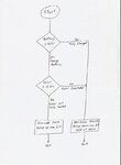
Your software should look something like this.
The PWM should ramp up or ramp down, to hold the solar panel at 15.0v (or whatever the MPPT voltage is set to).

solarflow.jpeg
 

Thanks, i have done the same way.
But, what are your observations with solar?
That is:when you directly hook up your battery say at 12.86V to the panel then what is combined voltage across them?
is it exact battery voltage? As i told you that when i did so the combined voltage of the system dropped down to 16.5V did the same happen in your case?If this happened then that means when at 100% duty cycle also panel voltage is not dropping to battery voltage and is remaining at 16V then, question of panel voltage further dropping to 14V doesn't arises.
And i am sure my algorithm is right because with 3 AA 9V batteries connected in series=27V(instaed os solar) gave me proper results.
 

Status
Not open for further replies.

Similar threads

Part and Inventory Search

Welcome to EDABoard.com

Sponsor

Back
Top