Continue to Site

Welcome to EDAboard.com

Welcome to our site! EDAboard.com is an international Electronics Discussion Forum focused on EDA software, circuits, schematics, books, theory, papers, asic, pld, 8051, DSP, Network, RF, Analog Design, PCB, Service Manuals... and a whole lot more! To participate you need to register. Registration is free. Click here to register now.

Designing a 12 V alarm with three triggers, a buzzer and indicator lights.

Status
Not open for further replies.

Paxman

Newbie
Joined
Mar 22, 2016
Messages
3
Helped
0
Reputation
0
Reaction score
0
Trophy points
1
Activity points
51
Hi guys!

First post on this forum. I'm from Sweden so English is not my native language so please be patient with my writing and that I might have trouble understanding advanced technical lingo. :)

What I would love to get some help with is as topic. I'm rebuilding the electrical system in my boat and one of the things I want to incorporate is an audible and visual alarm system to monitor three engine parameters.

There will be three triggers, two normally open (NO) and one normally closed (NC). I'd like each trigger to have a separate warning lamp but here is the kicker, I want only one buzzer to sound in case one, two or all triggers are tripped.

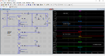
I have done some bench testing with diodes but it's not going well. This is the schematics that I thought would work:

Schematics warning system.jpg

I have tested with LEDs and a car battery but it seems the voltage is too low for the buzzer to sound. Strangely the buzzer I bought is said to work with a 6 to 12 volt span with a draw of 35 mA. The buzzer works fine if I connect it directly to the battery.

I have to admit this is the first time I use diodes so I'm a total noob...:oops:

Does anyone see anything wrong with my schematics and/or have any suggestion of how I can get this to work?

Oh, the "54" on the ignition lock is positive feed.

Cheers
Fred (from Sweden)
 

Add a transistor or two, somewhere, to perform switching action. It's too much to expect that current flow can perform all functions automatically.

- - - Updated - - -

You can add a diode network in the bias. They can perform diode logic. They only need small Ampere levels.
 

Hi BradtheRad!

Can you explain a little more how I should do? I'm really a noob to this.

Can I use any transistor? You say to add them "somewhere"...could you be a little more specific?

Sorry for being so clueless...

Also, thank's to admin for moving this thread to the more correct category.
 

To make progress you'll need to pick up some transistor theory, and learn by experimenting.

However come to think of it, an easier approach is to avoid putting the buzzer inline with the lamps. The aim is to provide both with greater voltage. Correct? Steps to take.

(a) Duplicate your schematic (the middle network part, that is).
(b) In one network, delete the buzzer and close up the gap.
(c) In the other network, delete the lamps and close up the gaps.

Redraw your schematic. Examine operation, to find out whether certain diodes are essential and some not.

- - - Updated - - -

Your schematic has switches which are normally closed, yet you want lamps to turn on when they open? This will require a different arrangement, namely by putting the switches in parallel with the lamps, I think. And a series resistor somewhere.
 

Oh, sorry...I should have explained the systems function in my first post.

When the ignition key is tured to "ignition" (step before the starter motor is engaged) the two sensors that are NC are supposed to trip the alarm with their respective lamps and the buzzer. These two sensors are "lack of cooling water flow" and "low oil pressure". The sea water pump is not running and the oil pressure is zero with the engine off. The NO switch is "high cooling temperature" so that one is obviously not tripped with a cool engine.

When the engine is started, the sea water pump starts pumping the water opening the switch for that and the engines oil pump gets the oil pressure up. With the engine running normal all three switches are open until one of the parameters triggers its switch.

When the engine is turned off the switches for water flow and oil pressure is going to trigger the alarm again.

The lamps are only supposed to light up when the switches are closed. This way I can see what has tripped the alarm. Say I'm driving my boat across the lake and the alarm goes off. Then I want to be able to look at the three lamps to see what switch is triggered. Maybe I got a plastic bag stuck in the sea water intake that has stopped the water flow.

When you say to duplicate the schematic, do you mean that each switch need to have two wires going to two different networks?

The aim is to have three monitors, each with their own lamp but sharing the same buzzer. The absolute simplest way to do this would be to do three different networks, each with its separate switch, lamp and buzzer. But where is the fun in that? :) I like challenges, only when you take on a challenge you learn and expand your knowledge!
 

I might be wrong but are the diodes in your schematic backwards?
 

My concept about duplicating the network. It shows only how to split off the buzzer current from the lamp current. It's simple and no doubt needs work, to make things turn on the way you wish.


You may need to add one or more diodes on the left, if the ones you installed on right are really needed.
 

By the way, a buzzer typically interrupts current off and on as it buzzes. This affects everything in its path. Things can behave unpredictably. It can be the reason why performance deteriorated when you put lamp and buzzer in series.

-------------------------------

Here is an example how to arrange for (a) switch-On bulb-Off, (b) switch-Off bulb-On. The upper resistor value is the result of experimentation, depending on how the switch and bulb interact.


- - - Updated - - -

Oh, the "54" on the ignition lock is positive feed.

Then post #6 raises a correct point about your diodes being drawn in reverse. And ignore the negative supply in my simulation above.
 

HI

Check this circuit.

I showed the sensors operating in the order you described in an earlier post.
I pick an arbitrary trigger time for the water temp alarm.
 

Attachments

  • BoatAlarm.png
    BoatAlarm.png
    50.2 KB · Views: 138

First test your circuit on a small scale- with three lamps and a buzzer and three diodes. Your original diagram is correct but voltages and currents may not be appropriate.

Make sure the diode orientations are correct.

Put a small cap across the buzzer.

Make sure the lamps can work with the specified voltages. Make sure when all the diodes are forward, the three lamps light up and the buzzer also works. If not, you will need transistor drivers for the three lamps.

To prevent sloshing, you need to ignore short pulses.

You also need to invert some of the signals as per your specifications.

Do it systematically and it will work. The idea is simple but a practical circuit will be having more components.
 

Status
Not open for further replies.

Part and Inventory Search

Welcome to EDABoard.com

Sponsor

Back
Top