Continue to Site

Welcome to EDAboard.com

Welcome to our site! EDAboard.com is an international Electronics Discussion Forum focused on EDA software, circuits, schematics, books, theory, papers, asic, pld, 8051, DSP, Network, RF, Analog Design, PCB, Service Manuals... and a whole lot more! To participate you need to register. Registration is free. Click here to register now.

Design of audio amplifier

Status
Not open for further replies.

sathiyanarayananL

Newbie level 6
Joined
Jan 9, 2016
Messages
14
Helped
0
Reputation
0
Reaction score
0
Trophy points
1
Activity points
122
hi,

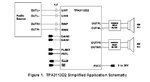
I would like to know what is the audio input positive and negative signal in general, also will it work if i interface the audio signal from mobile phone ( 3.5mm jack ) to the left and right positive pins and grounding the negative pins?

please find the attached image.

thankyou
 

Attachments

  • AUDIO_AMPLIFIER.jpg
    AUDIO_AMPLIFIER.jpg
    40.9 KB · Views: 78

You should be able to use the example schematic at page 18 of the data sheet. DO NOT connect the LINN and RINN pins together, use capacitors as shown in the diagram. You can connect the right and left channels from the 3.5mm jack to the LINP and RINP pins as shown.

Brian.
 
Figure 33 on page 18 in the datasheet shows single-ended inputs but the input signal source has no ground because it was written by a stupid little kid who recently graduated from school.
Doesn't anybody at TI check for errors like that?
 

It's more symbolic than a full design but Audioguru is right. The ground reference for the input signals is pin 8 of the IC.

Brian.
 

Status
Not open for further replies.

Similar threads

Part and Inventory Search

Welcome to EDABoard.com

Sponsor

Back
Top