Continue to Site

Welcome to EDAboard.com

Welcome to our site! EDAboard.com is an international Electronics Discussion Forum focused on EDA software, circuits, schematics, books, theory, papers, asic, pld, 8051, DSP, Network, RF, Analog Design, PCB, Service Manuals... and a whole lot more! To participate you need to register. Registration is free. Click here to register now.

Delta-sigma modulator runs well for a while then sticks to rails

Status
Not open for further replies.

palermo

Newbie level 6
Joined
Feb 16, 2012
Messages
11
Helped
0
Reputation
0
Reaction score
0
Trophy points
1,281
Activity points
1,357
Dear community,

I have designed a 1st order 1-bit delta-sigma modulator. I have implemented the fully differential architecture proposed on p31 of Schreier's "Understanding Delta-Sigma Data Converters" book. After running the simulation in Cadence, I import the data into Matlab to process it.

So as to have a high resolution fft, I want to run a simulation for 200 periods of input signal. However, resulting output signal is very well for first ~100 period and then sticks to the rails.

Do you have any idea why this happens?

Enclosed are the output graphics.

Thanks in advance!

edaboard1.png

edaboard2.png

edaboard3.png
 

Check the integrator output, does it saturate some where? I assume clocked comparator is working fine.
 

I think you should also reset the output to its appropriate Vref during the inactive phase.

Assuming a symmetric supply (i.e. VSS = - VDD), the half supply range is used as the Vref and -Vref (i.e. Vref = VDD/2 = |VSS|/2). The input amplitude is also limited to the same range. In fact, the sum of Vref and Vin is maximum 0.8 x VDD/2

What exactly do you mean by resetting the output during the inactive phase?

Just to clarify: My problem is that the output sticks to rails after ~100 period, although a sine wave input is applied all the time.
 

The phase when you connect ±Vref to the inputs.

When ±Vref is connected to the inputs, the output signal is (i.e. output of d flip-flop) is connected to the switches. Why should it be reset?
 

I don't see any d flip-flop in your above circuit. I suggested to reset the outputs of the fully diff opAmp simultaneously with the inputs, to avoid their floating to the rails.
 

I don't see any d flip-flop in your above circuit. I suggested to reset the outputs of the fully diff opAmp simultaneously with the inputs, to avoid their floating to the rails.

The comparator is latched. I implemented it as a d_ff following the comparator.
 

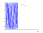
I have figured out what the problem is: The input voltage stays constant after a while!?! Somebody help!

edaboard4.png
 

The input voltage stays constant after a while!?!

I guess you mean the input voltage of the comparator, i.e. the output voltage of the fully diff opAmp, right?
In this case, track back the node voltages in the opAmp from its outputs to its inputs. Try and find out if bias voltages change with time, or which transistor(s) get out of saturation.
 

I guess you mean the input voltage of the comparator, i.e. the output voltage of the fully diff opAmp, right?

No, above the figure is the output of the vsine source from analogLib.
 

Most likely, you have set a cycle number for the sine source.
 

Most likely, you have set a cycle number for the sine source.

No it's clear, I didn't know that we can do that indeed. Well, after a successful simulation for 50ms, when I say direct plot, it does plot only until the time instance it gets stuck, i.e. until 18ms for above figure but not until 50ms. When I import this data to Matlab, I see this figure. The only hint I have, is this. Somehow, icfb is aware that there is something wrong; but it does run the simulation until 50ms without any error.
 

Yes that is correct, cadence wavescan tool does not load after 18ms.
 
Status
Not open for further replies.

Part and Inventory Search

Welcome to EDABoard.com

Sponsor

Back
Top