Welcome to our site! EDAboard.com is an international Electronics Discussion Forum focused on EDA software, circuits, schematics, books, theory, papers, asic, pld, 8051, DSP, Network, RF, Analog Design, PCB, Service Manuals... and a whole lot more! To participate you need to register. Registration is free. Click here to register now.
Operating in CCM allows an inductor with lesser saturation rating.
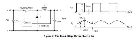
Notice if you reduce frequency, then you have the Ampere waveform traveling a large range between crest and trough. That is, between zero and a high peak (DCM).
However by switching at higher frequency, the AC waveform traverses a smaller distance. It develops greater DC component (Imin in your diagram)(CCM). Nevertheless there's a benefit because peak current is reduced in the inductor. Its saturation rating need not be as great as for a slower switching frequency.
This site uses cookies to help personalise content, tailor your experience and to keep you logged in if you register.
By continuing to use this site, you are consenting to our use of cookies.