Continue to Site
Follow along with the video below to see how to install our site as a web app on your home screen.
Note: This feature may not be available in some browsers.
Hi,
You are looking for a schematic? a ready to buy module? A complete power supply including enclosure? Industrial or some bench top device?
What does this "+/-" mean at the WATTs?
Why do you say 1800W, while 5A at the max output voltage of 75V, just gives 375W?
Klaus
Hi,Hi,
I'm not shure it works like expected.
2 things worry me:
1) MPPT on a 75V constant voltage source coming from the step up. MPPT tries to increase current ... and for now it's not clear why it should be limited to 5A. Usually a solar panel does not as a constant voltage source, but more like a constant current source. And thus the MPPT expects this behaviour.
2) Paralleling two SMPS is not a simple task. Each one tries to regulate a dedicated output voltage ... and you usually can't adjust both SMPS for reliable equal power sharing ... unless they are designed for this.
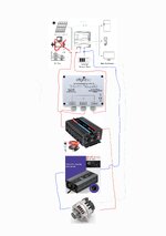
For a further discussion I recommend to draw a sketch about the devices and their wiring.
Klaus
How do you know that it limits at 5A? A 5A rated one just says it can deliver it, but does say nothing about how it reacts in overcurrent.a 5A limitation on the SMPS OUT will draw 30A on SMPS IN
I did try out its 1200watt little brother and that one had the same potmeters to adjust the va's. I measured 5a steady output at 65vcc and turned it down to 3,5 amps to limit the input amps even more. But somehow after a while it started to hickup and go on and off every 5 seconds. Then i measured 74voc at SMPS out and couldn't adjust the voltage anymore. Also i noticed a huge voltage drop when the device was going on and of becouse of some defect (not visual though, and the inverter was still generating +300watt in the few seconds it was on)How do you know that it limits at 5A? A 5A rated one just says it can deliver it, but does say nothing about how it reacts in overcurrent.
Some will deliver more, some may have a fuse that blows, some may truely limit, but not exactly at 5A. Some may go into hickup mode... or, or, or...
Klaus
Sometimes the advertisements on ali show a perfect product but then in real life it can be a different experience.there is no current limit on he Ali express converter - it is not controlled like a proper switcher
to work with MPPT, you need a soft rounded current limit.