Continue to Site

Welcome to EDAboard.com

Welcome to our site! EDAboard.com is an international Electronics Discussion Forum focused on EDA software, circuits, schematics, books, theory, papers, asic, pld, 8051, DSP, Network, RF, Analog Design, PCB, Service Manuals... and a whole lot more! To participate you need to register. Registration is free. Click here to register now.

DC-link capacitor ripple current

Status
Not open for further replies.

Rik797

Junior Member level 3
Joined
Oct 25, 2012
Messages
28
Helped
4
Reputation
8
Reaction score
4
Trophy points
1,283
Location
Bologna, Italy
Activity points
1,473
Hi guys!

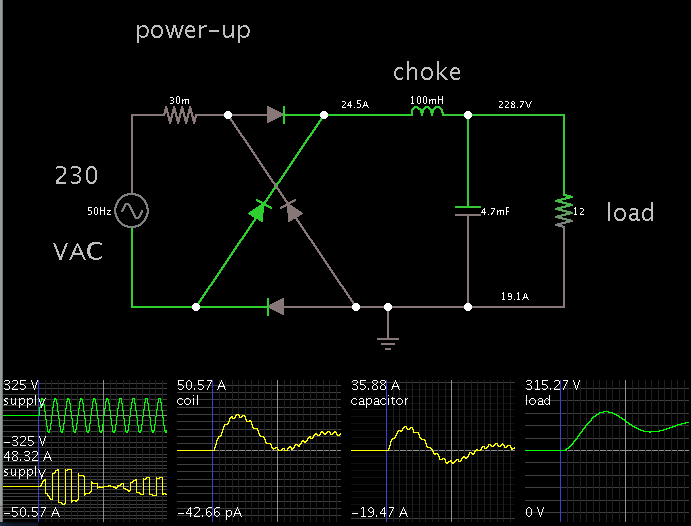
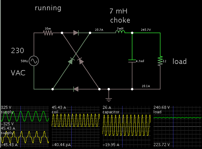
As last part of my switching mode power supply, I need to design the DC bus (or DC link). The equivalent load is 12 ohms (4200 W @ 230 Vac).
By connecting the rectified mains (230 Vac, 50 Hz) to a 4700-uF electrolytic capacitor, I obtain ripple current peaks of 200 A during the capacitor charge (100-Hz frequency).
Ripple current ratings of electrolytic capacitors, however, are usually lower by one order of magnitude (e.g. 20 A)!

What would you suggest me? I am doing something wrong?

Thank you in advance!

Rik
 

you should add a PFC circuit to avoid such ripple since you are dealing with 4200W
 
  • Like
Reactions: Rik797

    Rik797

    Points: 2
    Helpful Answer Positive Rating
Thanks picgak!
You suggest a passive PFC circuit between the mains and the capacitor?
 

What about a series choke (e.g. 0.5 mH) between the rectified mains and the capacitor?
Is it feasible?
 

What about a series choke (e.g. 0.5 mH) between the rectified mains and the capacitor?
Is it feasible?
It's the usual "passive PFC" method applied in VFD inverters. But it can hardly raise the power factor above 2/3 or so. Capacitor ripple current has to be determined as RMS value, it won't be larger than about 40 A even without a series inductor.
 
  • Like
Reactions: Rik797

    Rik797

    Points: 2
    Helpful Answer Positive Rating
Thank you FvM, you are correct! Although my inverter is not VFD.
If the ripple current has to be evaluated as an RMS value, than it turns out to be roughly 55 A without the inductor, 32 A with the choke.
Do you think it is a good choice, then?

Thanks!
 

If the ripple current has to be evaluated as an RMS value, than it turns out to be roughly 55 A without the inductor, 32 A with the choke.
Sounds like more than 4.2 kW load. In any case, you'll need some kind o low ESR capacitors to handle the ripple current.

The alternative is an active PFC with sine input current, but the design is more involved.
 
  • Like
Reactions: Rik797

    Rik797

    Points: 2
    Helpful Answer Positive Rating
Breaking the filter into multiple smaller parallel caps
ought to up your ability to get rid of the heat (goes
with surface area of the cans, while value tends to
go as volume).

The other, perhaps more severe, ripple current is on
the discharge side, a DC-DC converter imposes square
wave ripple equal to IOUT during the "on" time and
zero during "off" time. An input choke might smooth the
input peak current some but would be unacceptable
between the filter and the converter input rail.
 
  • Like
Reactions: Rik797

    Rik797

    Points: 2
    Helpful Answer Positive Rating
The other, perhaps more severe, ripple current is on the discharge side
In many cases, there will be low inductance foil/film capacitors that carry most of the high frequent ripple current.
 
  • Like
Reactions: Rik797

    Rik797

    Points: 2
    Helpful Answer Positive Rating
100 mH/20A is just unrealistic.

Yes, it is true that a smaller Henry value is needed, if the load is to get above 4 kW.

For comparison, here is my previous layout with a 7 mH choke. After some experimenting I found that is the Henry value that provides an output voltage of 230 V.


On startup, 153 A surge current goes through the capacitor. (That is, if the mains can provide it.)
 
  • Like
Reactions: Rik797

    Rik797

    Points: 2
    Helpful Answer Positive Rating
Thank you all very much!

On startup, 153 A surge current goes through the capacitor. (That is, if the mains can provide it.)
This should not be an issue since I will arrange a soft start circuit.

100 mH choke provides an output voltage that is, unfortunately, too low for my purposes.

An input choke might smooth the
input peak current some but would be unacceptable
between the filter and the converter input rail.
What about putting it between the bridge and the capacitor? May it resonate with the inverter, causing some destructive consequences?

DCbus2.png

In this simulation I used a 3-phase input with a half-bridge rectifier in order to get a 325 Vdc output.

Doubling the capacitance 4.7 mF + 4.7 mF also leads to interesting results, as the current is now split over two caps.

DCbus2ic1.png

The other, perhaps more severe, ripple current is on the discharge side
In many cases, there will be low inductance foil/film capacitors that carry most of the high frequent ripple current.
In fact, I arranged a couple of film capacitors on the inverter board, and the troubling current occurs during the charging phase of the electrolytic capacitor.

@BradtheRad: BTW, what is your simulating software?
 

You didn't yet mention three-phase supply. Half-wave rectifier isn't an option for a mains connected power supply, because DC current consumption from mains is strictly banned. This means, if considering three-phase input, then you have to choose three phase bridge and get 540 instead of 310 V bus voltage.
 
  • Like
Reactions: Rik797

    Rik797

    Points: 2
    Helpful Answer Positive Rating
In fact, I arranged a couple of film capacitors on the inverter board, and the troubling current occurs during the charging phase of the electrolytic capacitor.

With the system carrying 4 kW, you have dozens of amperes going back and forth through the capacitors. Besides the steel or copper leads, it means the contact point between the lead and the internal film.

A bank of capacitors will reduce the load on any one component. Notice that you must use a sufficient number, such that the failure of any one will not cause too much burden on the remainder.

@BradtheRad: BTW, what is your simulating software?

Falstad's interactive animated simulator at falstad.com/circuit.

Click the link below and it will open the falstad website, load my schematic, and run it on your computer.

https://tinyurl.com/mwzpecd

You can adjust values at will. Right-click on a component, and select Edit.
 
  • Like
Reactions: Rik797

    Rik797

    Points: 2
    Helpful Answer Positive Rating
Thank you BradtheRad for your reply.

FvM, I did not considered the issue you mention:
DC current consumption from mains is strictly banned
but it is true. I think I will simply revert back to my single phase design.

Do you think the choke as shown below is a good idea?

DCbus3.png
 

Do you think the choke as shown below is a good idea?
Basically yes. The inductor can be also connected in front of the rectifier, the current waveform doesn't change as long as it's discontinuous.
 
  • Like
Reactions: Rik797

    Rik797

    Points: 2
    Helpful Answer Positive Rating
Great, thank you!

The inductor can be also connected in front of the rectifier
I have seen that most chokes are common-mode inductors, thus the connection that you propose is quite convenient.
 

But a common mode inductor does not improve the input current power factor, or more exactly, only the small differential inductance part of a common mode choke does.
 
  • Like
Reactions: Rik797

    Rik797

    Points: 2
    Helpful Answer Positive Rating
I thought these ones
**broken link removed**
acted as two series inductors, by connecting them this way:

DCbus4.png

So you suggest a plain inductor, as in the diagram above the core easily saturates?
 
Last edited:

Status
Not open for further replies.

Similar threads

Part and Inventory Search

Welcome to EDABoard.com

Sponsor

Back
Top