Continue to Site

Welcome to EDAboard.com

Welcome to our site! EDAboard.com is an international Electronics Discussion Forum focused on EDA software, circuits, schematics, books, theory, papers, asic, pld, 8051, DSP, Network, RF, Analog Design, PCB, Service Manuals... and a whole lot more! To participate you need to register. Registration is free. Click here to register now.

dc current sensing problem in solar charger

Status
Not open for further replies.

Rajnaveen

Member level 2
Joined
May 11, 2014
Messages
42
Helped
0
Reputation
0
Reaction score
0
Trophy points
6
Activity points
307
Hi
I am using op amp as an amplifier to amplify a mV signal sensed through a shunt resistance in a solar charger that is integrated with a 5000W inverter . my problem is that when i run load at inverter there is some off set voltage at op amp due to ground difference . how to resolve the issue
.
 

Use a differential amp across the shunt, if you can. Or fix your grounding.
 

Sorry, my mind-reading skills are failing me; I can't visualize your schematic. Basically, you don't want the load current return running through the same conductor as your op-amp ground. Can I assume you are just monitoring the voltage one side of your shunt? And is it really a "shunt" as opposed to a SERIES sense resistor?
 
Yes you are right . I am taking voltage drop across shunt signal. that is connected between negative path of charging current .
Basically I am using a Buck converter for solar charger and output of solar charger is battery positive and negative terminal and the same battery is used for inverter input . shunt is placed between solar negative terminal and Battery negative terminal
.The signal of shunt is amplified with reference to digital controller ground . Analog and digital ground is separated by zero ohm resistance.
 

It's effectively impossible to get reliable readings from a low-ohmic shunt without 4-wire connection and differential sensing.

Instead of a true differential amplifier, it may be sufficient to connect the amplifier's ground reference to the ground sense pin of the shunt.
 
Hi,

It's effectively impossible to get reliable readings from a low-ohmic shunt without 4-wire connection and differential sensing.
This does not mean you have to buy a shunt with four connections. But you have to take care that through your sensing wires there is no (part of) load current.
I use 5mOhm smt resistors size 2512. Power traces from outside the package, the sense traces from the inner side of the pads (under the resistor).
The same can be done with thm resistors. Connect te power wires as usual and solder two extra sense wires to the resistor wires next to the resistor package.

Hope this helps
Klaus
 

Just as last part of KlausST's suggestion, elaborating the ground path will easily help. Please read about “star node” or “Kelvin connection”, then you will get the essence.


Quote from KlausST's :”Connect te power wires as usual and solder two extra sense wires to the resistor wires next to the resistor package.”
 
Last edited:

I still didn't understand why is called a "shunt" resistor when it's used in series.
Also, what is meant by "offset due to ground difference"? Is someone trying to say that measurements are possible even if the ground of the signal is not connected to the op-amp ground?
Someone please explain...
 

Hi mrinalmani,

offset due to ground difference

for sure the measurement ground should be the opamp ground.
But in reality you have stray resistance and (often even worse) stray inductance in your layout.

Especially with high current and fast switching you have different voltage in the same ground signal. You can´t suppose it to be zero.

To avoide wrong measurement you first need a low impedance shunt/resistor (metal strip) and a good layout with seperate power lines and signal lines.
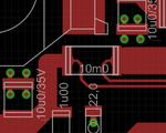
In my latest PCB layout you can see the big power traces connected to a 10 mOhms resistor and the sense traces to the opamp.
Kelvin.png
I know the copper traces are about the same resistance than the shunt, but with this wiring it causes (about) no errors.

Hope this helps
Klaus
 

Thanks for the reply. So that's the reason they call it shunt! which is actually in series with the power circuit.
Doesn't a ground plane eliminate ground bouncing?
 

Hi,

Doesn't a ground plane eliminate ground bouncing?

Nothing is perfect.... it reduces ground bounce...
 

Now, this is bad! I am in a design process of a HF inverter. The current through the PCB is as high as 80A at a frequency of 100kHz. (But ofcourse the high current traces will be accompanied with a thick conductor strip soldered on top)
The power-system ground including transformers, MOSFETS etc etc is common to the control-system ground including MCU, op-amp etc.
Does this call for a four-layer PCB? Or will two layers be sufficient with common ground plane for instrumentation and power components?
 

There are many ways to transmit remote current sensing to avoid ground shift. Often up 10% losses on power cables cause signal errors from ground shift, which requires copper conduit pipe or heavy wire to eliminate.

I have used these methods in the past; Your selection depends on accuracy, and bandwidth required.

- Tach circuit converting current to 1 shot repetition rate then sent tach signal as 1 bit in a spare channel of a telemetry data link using latch to prevent aliasing, used to monitor motor current in realtime.
- current loop 4~20mA industry standard.
- differential input and differential outputs in shielded pair.
- VCO, send voltage as a frequency with PLL using same VCO to convert back to voltage. Use much higher f than bandwidth needed.
- dedicated ground wire and signal pair ( used for long umbilical wires between launch site and control building >( several km)
 

Hi,

Does this call for a four-layer PCB?

A 4 laver PCB will improve this. If it is really necessary depends on what you need. Maybe that absoulte precision is not needed.
Many errors one can eliminate with analog filtering and compensation by software....

A cut in the gnd plane where you split the analog part from the high current high frequency part improves signal quality. Place the cut in that place where you expect that the power current travels the analog part.
But leave a solid connection. Often it is a good way to split the gnd plane ant the power input to the PCB, where the bigger connnection is to the power part and still a big connection is to the analog part.

Good luck

Klaus
 
"Place a cut.... but leave a solid connection"
Do you mean to say... leave a thin trace connecting the two lobes of the ground plane? If you have worked on something like this and have done such a thing before, I will be highly obliged if you kindly post a few or just one photo of such a PCB layout.

Do you think using 4-20mA current signal would be a practical decision? Also a mismatch of 4 to 5mV should be tolerable in my application. Is this requirement still very strict?
 

I think the original current sensing problem is partly confused by mixing it with general ground bouncing questions. The discussed 4-wire sensing will be needed for accurate low-ohmic shunt measurements in any case, either if the design uses 4-layer PCB with ground planes or comes along with simple two-layer technology. This is because mV voltage drops won't be tolerable for shunt sensing but don't involve a general signal quality problem. On the other hand, even massive traces and copper bars won't reduce voltage drops to a level that 4-wire shunt connections become obsolete.

The other point is a suitable layout of the switcher power circuit, considering not only DC current capacity of traces, but also circuit inductance, possibly skin effect and crosstalk to control signals.
 

That was the same problem with me but in digital ammeter...try to keep your op amp near to shunt and ground it with "Shunt Ground"....
 
mrinalmani,

Current shunts are usually 75mV or low enough to prevent temperature rise error of 0.4%/deg C so if 4mV is tolerable, then it implies you can tolerate 5% error. Be sure your heavy ground current shunt is adequately cooled, such as a ground side shunt thermally bonded but electrically isolated to a heatsink or similar result to avoid the 0.4%/deg C error.

A kelvin method implies no fringe E fields at the measurement points, which means the sample points are not at the very ends of the heavy shunt strip.

Heavy shunt strips will not prevent ground shift, from long heavy cables with only 75mV signal range, although one could tap into a fixed cable after calibrating two points with a 10A current source

In any case a shunt must also be sensed using differential traces at right angles to the current and cables also at right angles into differential high impedance amplifier. It is important to prevent inductive magnetic coupling voltage error between the high current conductors and the sense wires.

The answer is clearly a differential amp with dedicated wires leading away at 90 deg and not grounded to the ADC board. A CM ferrite choke may also be needed as differential amps have poor RF CMMR.

If you short the shunt and still get a signal out, you have a CMMR problem.
 
Last edited:

Status
Not open for further replies.

Similar threads

Part and Inventory Search

Welcome to EDABoard.com

Sponsor

Back
Top