Welcome to our site! EDAboard.com is an international Electronics Discussion Forum focused on EDA software, circuits, schematics, books, theory, papers, asic, pld, 8051, DSP, Network, RF, Analog Design, PCB, Service Manuals... and a whole lot more! To participate you need to register. Registration is free. Click here to register now.
Hi,
The blue probe seems to be the culprit. I connected another probe in its stead and the waveform is clean. I did probe check and followed the instructions to turn the yellow screw with a non-metallic object, but the waveform does not straighten. I guess that probe has gone bad.
Anyways, I will be doing more testing today and tomorrow. Will share a picture of the circuit, but to tell you, it is really shaggy.
Hi,
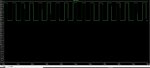
I have built & tested the DC current sensing ckt successfully. I have attached the final schematic. Some components are not populated R163, C160, C88, C159, C95. R138 is a short. Now I am facing another issue regarding the voltage pulses being generated at junction of D13 & D14. These are pulses above 24V pedestal and upto 6-9 V DC. The pulse pattern is decided by switching of Q9 & Q7. This is then passed through R146 to the output.
Now the pulses are OK when operating at moderate loads of around 50-100 mA. But my load will be around 800mA. The moment I increase my load above 100mA or so, the voltage starts dropping. Especially the part above 24V pedestal starts dropping. The 24V & 34V are both strong supplies with at least 3A current capacity. Also the Q7 is a power MOSFET. So that should not be a problem.
Why could this be happening?
Any help will be appreciated.
Have you examined with voltmeter or oscilloscope what amount of voltage is being dropped across the MOSFET when the droop happens and/or between gate and source? It may not be a relevant issue, just an idea.
- - - Updated - - -
**broken link removed** for datasheet fans
- - - Updated - - -
Without having looked at anything in-depth much (haven't simulated it yet), would making R3 (NPN base) resistor larger, or maybe smaller, improve the output compliance? Also, is it possible that the MOSFET body diode has anything to do with the problem? Probably not.
depending on switching frequency and duty cycle the circuit: R139, R131, C96, R140, R133, C97 will create a relatively low impedance. Maybe this can cause problems.
The input voltage of the comparators may be higher than the specified limits. In your case it can be 2.5V +/-5V, this means: -2.5V...+7.5V (depedning on waveform and filtering).
Check this with a scope and the datasheet.
Hi,
You are right. I removed the comparators to be on a safer side while increasing the load current. I have kept a gain of 50 for LT6100. Hence, when I increase the load current about say 130mA, the output of the LT6100 (current sense amp) hits saturation (0.13mA*0.75ohm*50 = 4.875V).
I read the LT6100 datasheet and it says the VCC can go up to 36V. I kept the load current at 100mA (Vout = 3.75V) and slowly increased the VCC of LT6100. The moment I reached 5.5V from 5V, the output jumped from 3.75V to VCC.
I went through the datasheet of LT6100 again but could not find any clue.
My calculation was the if I hit a load current of 800mA, the Vout will be 0.8*0.75*50 = 30V max. Hence I can keep the VCC of LT6100 to 34V, which i already have in my system.
I could keep the min gain of 10 for LT6100 but then the pulses detected by comparator will be as small as 150mV (0.02*0.75*10 = 150mV for 20mA pulse).
This site uses cookies to help personalise content, tailor your experience and to keep you logged in if you register.
By continuing to use this site, you are consenting to our use of cookies.
")