Continue to Site

Welcome to EDAboard.com

Welcome to our site! EDAboard.com is an international Electronics Discussion Forum focused on EDA software, circuits, schematics, books, theory, papers, asic, pld, 8051, DSP, Network, RF, Analog Design, PCB, Service Manuals... and a whole lot more! To participate you need to register. Registration is free. Click here to register now.

[SOLVED] DC bias point dropping during STB analysis

Status
Not open for further replies.

Kanishmas

Newbie level 3
Joined
Feb 3, 2018
Messages
4
Helped
0
Reputation
0
Reaction score
0
Trophy points
1
Activity points
45
Hello All,

I am wondering if you can help me with an issue I am running across with a fully differential amplifier.
I am able to set all my FETs in saturation and the common feedback circuit I am using appears to be working.
When I run the STB analysis using the cmdb probe and run a DC analysis first, some of the first and second stage amplifiers present are no longer in saturation and the current value I am reading changes from a 2mA (main tail current) value down to 50ish uA.
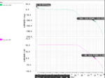
When I check the closed loop gain and phase graphs, the gain graph appears to be in the negative range -80dB until the graph gets to frequency 10^7ish Hz and then the graph suddenly drops to -100dB, and then it just starts increasing towards a-30dB value. The phase graph starts at -160 degrees and at 10^7ish Hz it goes up to -50 degrees and then it goes down to -300 degrees. STB response.PNG

Additional information: Open loop gain gives me a gain of 62dB with a phase margin of 60ish degrees.


Let me know if you can help me with this issue?

Thanks.
 

The Bode-plot of a non-working amp isn't really helpful. You'd show its schematic, once working & once not working, with backannotated node voltages (and branch currents, if possible).
 

Getting a different operation point in stb analysis suggests that you have somehow corrupted the DC feedback configuration or applied an unsuitable DC input level.

You didn't show the simulation circuit, so we can only guess how you achieved this. If you have difficulties to keep the intended operation point in your stb setup, there's an option to load the DC bias point from a previous analysis instead of calculating it in the stb circuit, review the reference manual.
 
Sorry about the lack of details. First, thanks for the reply. I figured I should have attached the schematic from the beginning.

Some details on this circuit, C23 and C22 are the load caps. They are both 1pF. Any other cap present, has a load of 10pF. I have the feeling the feedback circuit setup is the one that is causing the issue. Additionally, any resistors present have a value of 1T.
One more thing, disregard the second stages. I am trying to figure out why I can't even get the first stage running.
Non Working Circuit.pngWorking Circuit.png
Let me know if you need more details.

Thanks!
 

I was not sure how to update on this thread.
I believe the original picture I had shown you did not have the first stage voltage output matching VCM. You can see now it is close to 600.9mV (VCM=600mV)
Once again please disregard the second stage.
The first picture here should show you the DC operating point of my amplifier design:
CMFB_DCoperatingpoints.png

The second picture here shows you the STB analysis I am trying to run. You may notice I am using capacitors for the output feedback going back to the input terminal of my first stage differential amplifiers. There are also capacitors at the terminals where the differential inputs are applied. Both feedback capacitors (C24 and C25) and "input capacitors" (C26,C27) have a value of 10pF. The load capacitors (C22 and C23) have a value of 1pF. Any resistors present on my schematic have a value of 1Tohms.

CMFB_analysis.png

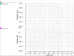
This is the current Gain and Phase response I get when I run the STB analysis:
CMFB response.PNG

I am wondering whether this is telling my circuit is unstable? What kind of procedure could I follow to fix this issue?
 

I am wondering whether this is telling my circuit is unstable?

I don't think so: A circuit with gain<1 will never be unstable. When your CMFB (current) gain reaches =1 (around 500MHz), it still has a PM>5° .

Re. CMFB-analysis.png : I think your input voltages Vin≈200mV - apparently due to the modeled gate current - put your diff amp out of its common mode range - that's why the MOSFETs M5..M8 are no longer in saturation.

What kind of procedure could I follow to fix this issue?

Instead of the 1TΩ resistors R13-R14 use huge inductors.
 
Hello, thanks for the reply.

These were my input signals:
Vin+ = 750mVdc, 500mVac 0 phase
Vin- = 750mVdc, 500mVac 180 phase

Replacing R13-R14 for inductors in the range of THenries worked. I connected my second stage and this is what I got:
02042018 0539PM.PNG02042018 0539PM.PNG


Thanks for your help!
 

Status
Not open for further replies.

Similar threads

Part and Inventory Search

Welcome to EDABoard.com

Sponsor

Back
Top