Continue to Site

Welcome to EDAboard.com

Welcome to our site! EDAboard.com is an international Electronics Discussion Forum focused on EDA software, circuits, schematics, books, theory, papers, asic, pld, 8051, DSP, Network, RF, Analog Design, PCB, Service Manuals... and a whole lot more! To participate you need to register. Registration is free. Click here to register now.

Current transformer resolution

Status
Not open for further replies.

gehan_s

Member level 3
Member level 3
Joined
Aug 31, 2012
Messages
62
Helped
3
Reputation
6
Reaction score
3
Trophy points
1,288
Location
Sri Lanka
Activity points
1,799
Hey all,

I need to measure an AC current of 0-6A rms using a CT. I have searched for CTs in the internet and found out that many of them go upto about 30A (some of them higher). If I use one of them (max 30A) will it reduce the resolution of the detected current ?

If so how can I increase the resolution ?(I am thinking of measuring atleast 50mA increments)

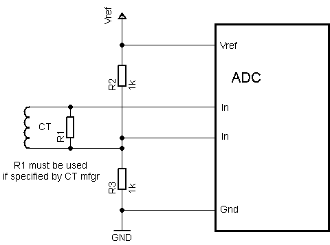
Also please tell me how to interface the CT to the PIC

thanks in advance !!!!!!!!!!!!!!!
 

picgak

Advanced Member level 1
Joined
Oct 13, 2011
Messages
407
Helped
101
Reputation
202
Reaction score
102
Trophy points
1,323
Activity points
3,177
connect CT to a precision rectifier using opamp and use a amplifying stage using opamp so that the maximum v is within 5v dc use a zenr for protecting the pic input
 

Tahmid

Advanced Member level 6
Joined
Jun 17, 2008
Messages
4,752
Helped
1,796
Reputation
3,584
Reaction score
1,653
Trophy points
1,413
Location
Silicon Valley, California, USA (from Dhaka, Bangl
Activity points
30,537
Use a load resistor at the output of the current transformer.

Here's one way you can interface the current transformer:
3722138400_1353921228.png
 

madhusuthanan

Full Member level 3
Full Member level 3
Joined
Jan 3, 2012
Messages
188
Helped
8
Reputation
16
Reaction score
8
Trophy points
1,298
Location
madurai
Activity points
1,963
use a burdon resistor llel to CT. then you use precision rectifier signal, it's o/p range is max of 5v. then o/p given to the adc i/p of the pic microcontrller.
 

klystron

Advanced Member level 4
Joined
Jul 11, 2002
Messages
1,011
Helped
193
Reputation
386
Reaction score
179
Trophy points
1,343
Location
South Africa
Activity points
4,513
Use multiple primary turns (loop your load current wire multiple times through the CT). This will improve the CT resolution.
 

babatundeawe

Full Member level 5
Full Member level 5
Joined
Apr 12, 2007
Messages
244
Helped
16
Reputation
32
Reaction score
12
Trophy points
1,298
Location
Nigeria
Activity points
2,738
Use a load resistor at the output of the current transformer.

Here's one way you can interface the current transformer:
3722138400_1353921228.png

tried making this circuit but i cudnt get the values stable on my display. when i measured the output i cudnt get a dc outptu except ac output can u or someone explain how to get dc output for interfacing with micro.

secondly the output is very low in the range of millivolt, i know i can amplify it but the output is still oscilating please help
 

gehan_s

Member level 3
Member level 3
Joined
Aug 31, 2012
Messages
62
Helped
3
Reputation
6
Reaction score
3
Trophy points
1,288
Location
Sri Lanka
Activity points
1,799
Hi babatundeawe,

Well you are measuring a AC current. So it must vary with time. When you sample the voltage what you are getting is instantaneous values.

Regards
 

babatundeawe

Full Member level 5
Full Member level 5
Joined
Apr 12, 2007
Messages
244
Helped
16
Reputation
32
Reaction score
12
Trophy points
1,298
Location
Nigeria
Activity points
2,738
thanks gehan. for ur resonse

please can you expantiate further especially how i can use the instantenous voltage to calculate the current and how can i use microcontroller adc to get these values

thankss
 

picgak

Advanced Member level 1
Joined
Oct 13, 2011
Messages
407
Helped
101
Reputation
202
Reaction score
102
Trophy points
1,323
Activity points
3,177
please can you expantiate further especially how i can use the instantenous voltage to calculate the current and how can i use microcontroller adc to get these values

thankss
the output of the CT can be bridge rectified and filtered for a stable reading
 

babatundeawe

Full Member level 5
Full Member level 5
Joined
Apr 12, 2007
Messages
244
Helped
16
Reputation
32
Reaction score
12
Trophy points
1,298
Location
Nigeria
Activity points
2,738
the output of the CT can be bridge rectified and filtered for a stable reading

considering forward voltage of rectifying diode and the voltage output level (in mV)of CT's its difficult to rectify and get an output. i ve tried different precision rectifier found on this site but none is giving me a pure dc output. please what do u advice
 

madhusuthanan

Full Member level 3
Full Member level 3
Joined
Jan 3, 2012
Messages
188
Helped
8
Reputation
16
Reaction score
8
Trophy points
1,298
Location
madurai
Activity points
1,963
hi,

the output of the CT should be precison rectifier & reading si read in microcontroller.

- - - Updated - - -

this is useful link in eada board

https://www.edaboard.com/threads/265127/
 

Status
Not open for further replies.

Similar threads

Part and Inventory Search

Welcome to EDABoard.com

Sponsor

Top