evandro.bubiak
Newbie level 5
Hi, I am trying to make a current transducer with full differential output. It will be used for data acquisition.
The transducer uses a isolation amplifier optocoupler (U1) and a full differential instrumentation amplifier with a integrated ADC driver (IC1).
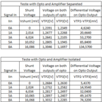
Everything is OK to the isolation amplifier, when I put 8 A on the input I get the correct output on the TP2 and TP3. But, when I connect the isolation amplifier output (U1) to the input of the differential amplifier (IC1) the output TP2 and TP3 goes down to the half of the value.
I tried to put a 1Mohm resistor on the inputs of the amplifier and even so the output of the opto drops to the half. As I know the current on the input of the amplifier was supposed to be insignificant (correct?) why could this be happening?
Need some help to understand whats going on. The voltage supplies are ok, the board is ok, I can't figure out whats happening.
Thanks.

