Welcome to our site! EDAboard.com is an international Electronics Discussion Forum focused on EDA software, circuits, schematics, books, theory, papers, asic, pld, 8051, DSP, Network, RF, Analog Design, PCB, Service Manuals... and a whole lot more! To participate you need to register. Registration is free. Click here to register now.
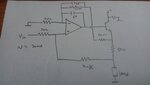
The first of post#5 is basically the same as the one of post#1.
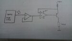
The other is better suited to your needs - at least I think so.
Give more informations:
* power supply
* DAC output voltage range
* desired speed / settling time / upper frequency limit
* load resistance range
* desired accuracy, precision
* other requirements
You will find a lot of 4..20mA circuit discussions in this forum.
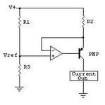
To ease the design I recommend a VCC referenced load
To improve accuracy I recommend to use a mosfet instead the bjt.
1. You need a differential amplifier topology to make the output current independent from supply voltage variations.
2. A bipolar transistor introduces a considerable error by its base current. The suggested circuit uses a darlington transistor to reduce the error below 1e-4.
3. As shown, the output current is proportional to input control voltage. To introduce 4 mA offset, an additional reference voltage and respective circuit modification is required.
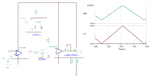
For 4..20mA outputs I recommend to add some headroom. I often go to 0..24mA.
The adjustment of 4.00mA and 20.00mA can be easily made by software. Without drift with time and temperature.
This site uses cookies to help personalise content, tailor your experience and to keep you logged in if you register.
By continuing to use this site, you are consenting to our use of cookies.