surreyian
Member level 3
hello,
How do we know which way is the correct connection?
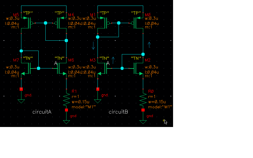
here is my understanding why circuit B doesnt work. But i cannot put my head around why circuit A works.
in circuit B. Break loop at A and inject a signal. If A increase then causing M1 to go Low, giving more current in M0 and M2. The negative feedback resistor R0 will reduc the over gain, hence over time, the circuit will stuck at zero. Is this understaning correct?
Cirucuit A has the correct connection is the working circuit, can someone help me to understand why we have to connect this way.
How do we know which way is the correct connection?
here is my understanding why circuit B doesnt work. But i cannot put my head around why circuit A works.
in circuit B. Break loop at A and inject a signal. If A increase then causing M1 to go Low, giving more current in M0 and M2. The negative feedback resistor R0 will reduc the over gain, hence over time, the circuit will stuck at zero. Is this understaning correct?
Cirucuit A has the correct connection is the working circuit, can someone help me to understand why we have to connect this way.