Continue to Site

Welcome to EDAboard.com

Welcome to our site! EDAboard.com is an international Electronics Discussion Forum focused on EDA software, circuits, schematics, books, theory, papers, asic, pld, 8051, DSP, Network, RF, Analog Design, PCB, Service Manuals... and a whole lot more! To participate you need to register. Registration is free. Click here to register now.

Current Limter Design, constant voltage

Status
Not open for further replies.
Yes it will regulate precisely providing more than 1 ampere. For more precision see precations in post.
 

Attachments

  • lm317-.png
    lm317-.png
    15.9 KB · Views: 59
Last edited:

If I understand right, you already have a constant voltage of 10 V and want to add a current limiting feature. That would be different from the operation of a LM317 or other voltage regulator that has a considerable voltage drop and needs e.g. 12 V or an even higher input voltage to achieve regulated 10 V. Perhaps you can clarify this point?

On the other hand, any practical current limiter circuit will have an inner resistance resulting at least in a small voltage drop. Strictly speaking, you'll need both, a current sense means and a switch to disconnect the load in case of overcurrent. Both have a resistance and some voltage drops.

If you revert to a state-of-the-art voltage calibrator instrument, it usually has a built-in programmable current limiter, as you are asking for. But it senses the output voltage at the terminals or even at the load, so any internal voltage drops or cable losses can be compensated. A current limiter placed behind a two terminal voltage source can't compete with this design.
 

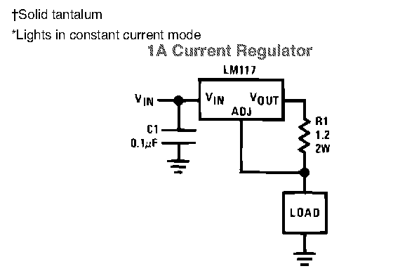
If i were to supply the system with 14.5 will 10 volts drop appear across the load, and it will not drop?

If your input voltage won't drop below 13V, you will be able to get with LM317 the constant 10V output.
The extra 3V are needed as follows:

2V for LM317
1V for the current limiting resistor using a small npn transistor.

If you are interested I will draw the circuit for you.

Kerim

---------- Post added at 00:52 ---------- Previous post was at 00:46 ----------

Yes it will regulate precisely providing more than 1 ampere. For more precision see precations in post.

As you wish, if you think that Rs is inserted deliberately here.
 

As you wish, if you think that Rs is inserted deliberately here.
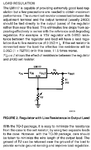
From datasheet, current regulation aplication.
78_1311026822.png
 

Attachments

  • lm317-----.png
    lm317-----.png
    1.9 KB · Views: 58
Last edited:

These are ok... But between Vin and the load there must be:

Vdrop = (Vin - Vout) + (Vout - Vadj)

The drop is therefore:
2 + 1.25 = 3.25 V
I think it is rather a high value for just a protecting purpose.

Don't you agree with me? ;-)

Kerim
 

As FvM has elaborated this situation very well. Current sensor and sithing device, both will drop..I may go for using hall efect current sensor and reed relay.It takes some time to burn the pot so relay can also be used. But here i think it is a simple solution.
 

You are right... But in this simple case here, a drop of about 0.7V to turn on an npn transistor to limit the load current at 200mA is not a very bad solution I guess. And the power dissipation of the limiting resistor would be around:
Pdis = 0.7V * 200mA = 140 mW
a reasonable value for 400 or 500mW resistor type.

Added:
After all, it seems the original poster has solved his problem since he didn't ask me to draw the circuit of a possible solution for him.
 

Better use fet with low Rds-on like irf1404 with 4mOhm resistane. in fact It seems situation is not that critical it is just a matter of adjusting a mechanical pot and protecting it from over current damage. Operational amps can detect current in wire leading to that pot.
 

To be honest, I couldn't figure out yet the relation between the max 200mA and pots in Kohms up to 100K.
Even if the pot is 1K only, 200mA * 1K = 200V ! I think something is missing.
 

When the pot is shorted the voltage goes right to ground and because there's like 5-6 ohms in the wire the current is about 1.5 amps and that will destroy a pot. Btw these pots we make are high precision I work for Betatronix as an intern
 

I will be adjusting the load resistance from between 750 - 100k ohms and the voltage drop needs to stay at 10 volts.
For min 750 ohms, 13ma is drawn. Normally adjustments does not require to be at extreme + or- . A resistor in series with pot is all you need. It also helps to extend usable range with more precision. If there is no resistance in series during adjustment pot is rotated to extremes it effectively shortens the supply and burns. For just 13ma shunt regulator can also be used easily.
 
Last edited:

Also 200 mA is just an arbitrary value that I think is a good cutoff point.


If you show how exactly pot is connected wth respect to supply, why center leg is connected with supply,what are the current and voltages requirments. What is the load on the pot . abetter solution can be made
 

The current when the pot is hooked up is usually <10 mA for 1k ohm, its just when the pot is shorted the current usually goes up to about 1.2 A because the only resistance is the wire however... the current still goes through the pot and it burns it up within seconds. Thats why i need something that shuts it off fast which is why the use of a LM317 seems perfect because BJT's turn off very fast. I need to order a couple of these and see how it works

---------- Post added at 08:16 ---------- Previous post was at 08:11 ----------

Also the way the pot is connected is exactly like a resistor. Its put into the circuit just like that, in one node out the other.

---------- Post added at 08:24 ---------- Previous post was at 08:16 ----------

Now i have only taken 1 electronics class and i am trying to learn as i go but can someone explain how a voltage reference works? and is that a way to limit the current in the system? I really would like to have 10 volts from the supply and not have to adjust it to a different value every circuit. is it always going to be 13.25 volts with an lm317 or will it be 13.35 volts one time?
 

I am just curious why you have no choice but do a short at the output.
By the way, when I draw the circuit that shuts off LM317 at 200mA output (also I wonder how you estimated it), I remembered that it just reduces the output voltage from 10 to 1.25v and limits the current at about 200mA. The ideal solution is to cut off completely the output current. So I added a small n-channel MOSFET in series with the load and a positive feedback for latch up (otherwise the circuit would oscillates). In brief, I am afraid that I can't help on something I imagine which may be not the real thing you have... like solving a math problem with 1 equation having two unknowns. So I wish you good luck.
 

A voltage reference is an electronic device that produces a fixed (constant) voltage irrespective of the loading on the device, power supply variations, temperature changes, and the passage of time. The most common voltage reference circuit used in integrated circuits is the bandgap voltage reference. A bandgap-based reference (commonly just called a 'bandgap') uses analog circuits to add a multiple of the voltage difference between two bipolar junctions biased at different current densities to the voltage developed across a diode
A voltage reference circuit contain all the components needed in order to limit the current output also. The circuit is designed to provide a high precision voltage reference to minimize voltage drift and to operate over a large temperature range. No need for adjustments, just power up and you obtain the requested 10V power supply including the protection for short-circuit. For additional details need to read datasheet.


Voltage reference - Wikipedia, the free encyclopedia
**broken link removed**
 

Kerimf

When we are trimming the pots to make the ideal resistance: somtimes particles cause a short, wires touch and cause a short, or the wiper touches the end and causes a short. In the case that it does happen i just want to protect the pot from being destroyed.

Mister_rf

I will read up a little more on this voltage reference, it seems to be exactly what i am looking for

---------- Post added at 09:08 ---------- Previous post was at 09:03 ----------

mister_rf

It seems like there a lot of different types of voltage references, is there one in peticular that you would recommend?


Kerimf

We normally dont use any type of protection when we trim the pots so; our circuit is just a power supply connected to the pot and the pot is connected to ground. Just a simple 1 loop, single resistor circuit, which is why i want to add the current limiter between the power supply and the load. however it doesnt necesarily have to be before the load i just want to protect the pot from too much current
 

No special requirements for this application, need to choose some circuit to output 10V and to support a minimum 10mA on load. I guess should be selected the cheapest option available on the market.
REF01
http://www.analog.com/static/imported-files/data_sheets/REF01.pdf

Also you can buy
LM4040=precision micropower shunt voltage reference – to be used like a normal zener diode (15mA)
**broken link removed**
 

thanks for the help, i ordered the parts, now i will just wait for them to come in. They should be in Friday so i will give you feedback at that time.
 

Status
Not open for further replies.

Similar threads

Part and Inventory Search

Welcome to EDABoard.com

Sponsor

Back
Top