jdimeglio
Junior Member level 1

- Joined
- Mar 19, 2014
- Messages
- 19
- Helped
- 0
- Reputation
- 0
- Reaction score
- 0
- Trophy points
- 1,281
- Location
- Australia
- Activity points
- 1,533
help
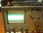
I have an oscilloscope that's malfunctioning - i actually have the circuity diagram for it too - including the CRT. :-| Truth is i'm still very much a newbie when it comes to CRT. I understand the theory but no experience in repairing them. The circuit is pretty simple - back when resisters where 1cm long and capacitors where big and fat. (ie: 1979 sort of stuff)
The problem
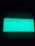
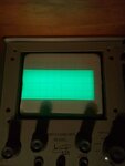
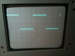
The problem i'm having is - instead of a single horizontal scan line, i get multiple horizontal scan lines. (see attached image).
If i'd have to guess it be something like 10 of them. That's 10 scan lines all bunched together.
Its as if the focus is out - way out. I've check the focus and it "works" - its only suppose to focus one scan line deep and it seems to be doing that. Hard to explain but you can see it working. I've also measure it and the focus is "correctly" applying ~800v-~1200v to the CRT.
I've checked the vertical amp, which control Y defection plates and works. Also if i feed in a single say a 1khz 4vpp square wave, instead of a nice single crisp scan line, i get a this big fat (10 wide) scan lines, but the Y deflection seems to be "working". And of course being a CRO, moving the wave form via the X&Y controls all seem to work too.
The horizontal amp looks like its working - i mean there as 7400 TTL nand gate that does some tricky switching, but roughly measuring the voltage and waveforms seems to be there. The horizontal amp circuit also does the blanking (as well as the alt (dual channel display) and add (adding both channels to the vertical amp)
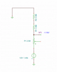
My question is would the FBT (or circuity) be the cause. The unfortunate part is none of my test equipment is rated above 750ac - so im not able to place any test probes in that area? I was thinking of placing a large 1M 10W resister in the circuit and measuring that - but don't know if that works or if it will load the diode pump circuity too much.. - Any ideas?
Has any one seen something similar? Could the blanking circuity be the cause? Looking at the capacitors (visually) nothing looks strange, no bulges or anything like that. The diodes and the bipolar transistors all conduct.
I'd hate to retire my trusty CRO.
Thanks for any help in advance.
joe

