Continue to Site

Welcome to EDAboard.com

Welcome to our site! EDAboard.com is an international Electronics Discussion Forum focused on EDA software, circuits, schematics, books, theory, papers, asic, pld, 8051, DSP, Network, RF, Analog Design, PCB, Service Manuals... and a whole lot more! To participate you need to register. Registration is free. Click here to register now.

create 100 random LFSR source inputs for a circuit in HSpice

Status
Not open for further replies.

Negneg

Newbie level 6
Joined
Apr 15, 2015
Messages
12
Helped
1
Reputation
2
Reaction score
1
Trophy points
3
Activity points
108
Hi,

I'm trying to generate 100 different source LFSR signals (just to have random 0/1 inputs) to give to a NAND gate as input in HSpice. Is there any way to generate such wave in a loop or something? For example a way to change the taps numbers ( [5, 2] to different numbers in vin1 and/or add more taps like [10, 5, 3, 2] in vin2 in the examples below) in a loop to get 100 different waves. I tried using sweep and monte, however I'm not sure if they are actually helpful!

Code:
.tran .1ps 10ns
Vin1 in1 0 LFSR (0 0.9 0 10p 10p 10e+9meg 1 [5, 2]) 
Vin2 in2 0 LFSR (0 0.9 0 10p 10p 10e+9meg 1 [10, 5, 3, 2])
Thanks!
 
Last edited by a moderator:

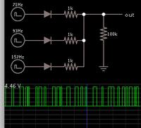
Suppose you mix three signals at different frequencies? These can be sinewaves, or they can be pulsed DC at different duty cycles.

Sum the signals through resistors.

Then feed the summed signal to a logic gate or Schmitt-Trigger, to end up with quasi-random pulses of various widths.
 

Thanks for your reply!
However, I don't really want to add anything to the circuit! Since, I'm looking at the aging of the circuit using MOSRA simulation! What I really want is a random pulse generator for #n times (e.g. 100 times) to measure the aging caused by different input wave forms on a logic circuit.
Anyway, I found a way to do that using .alter, now my question is if there is any way to call .alter in a loop of 100 changing the taps inside the loop. Also, .alter produces #n outputs, is there any way to append them all in one output?
Here is the solution I found so far:
Code:
.param Supply=0.9 
.param lambda=0.016u
.param fanout=4 
.options post
*****************************************************
* Define power supply
*****************************************************
.global Vdd Gnd
Vdd   Vdd   Gnd   'Supply'
*****************************************************
* Define Subcircuits
*****************************************************
.subckt inv In Out N=256n P='N*pnratio'

m1    Out In Gnd Gnd nmos l='2*lambda' w=N
+                 as='5*lambda*N' ad='5*lambda*N'
+                 ps='N+10*lambda' pd='N+10*lambda'
m2    Out In Vdd Vdd pmos l='2*lambda' w=P
+                 as='5*lambda*P' ad='5*lambda*P'
+                 ps='P+10*lambda' pd='P+10*lambda'
.ends
*****************************************************
* simulation netlist
*****************************************************
x1    In1    out   inv   
*****************************************************
* Stimulus
*****************************************************
Vin1 In1 0 LFSR (0 'Supply' 0 10p 10p 10e+9meg 1 [10, 1]) 
*****************************************************
* Measurements
*****************************************************
.param pnratio = opt1(2, 0.5, 3)

.tran .1ps 10ns

.alter 
Vin1 In1 0 LFSR (0 'Supply' 0 10p 10p 10e+9meg 1 [10, 2]) 
.alter 
Vin1 In1 0 LFSR (0 'Supply' 0 10p 10p 10e+9meg 1 [10, 3]) 
.alter 
Vin1 In1 0 LFSR (0 'Supply' 0 10p 10p 10e+9meg 1 [10, 4]) 
.alter 
Vin1 In1 0 LFSR (0 'Supply' 0 10p 10p 10e+9meg 1 [10, 5]) 
.alter 
Vin1 In1 0 LFSR (0 'Supply' 0 10p 10p 10e+9meg 1 [10, 6]) 
.alter 
Vin1 In1 0 LFSR (0 'Supply' 0 10p 10p 10e+9meg 1 [10, 7]) 
*****************************************************
* End of Deck
*****************************************************
.end
 
Last edited by a moderator:

Thanks! That's good for having a completely random (LFSR is psudo-random) wave form. However, to get 100 different wave samples from that circuit, I still need some sort of loop!
 

Hello,

Did you find a better solution for this problem? Im looking for the solution as well...

Thanks
Bo
 

I think you'd be better off simply bounding the problem with
static "1", static "0", and a couple of duty cycles and clock
frequencies (in digital, hot carrier charge is accrued mainly
during transitions, so frequency is a primary factor) between.

I don't see randomness or pseudorandomness as having much
value in real or simulated reliability testing. Better to exercise
the things you need to exercise more deterministically, so
that you gain repeatability.
 

Status
Not open for further replies.

Part and Inventory Search

Welcome to EDABoard.com

Sponsor

Back
Top