Continue to Site

Welcome to EDAboard.com

Welcome to our site! EDAboard.com is an international Electronics Discussion Forum focused on EDA software, circuits, schematics, books, theory, papers, asic, pld, 8051, DSP, Network, RF, Analog Design, PCB, Service Manuals... and a whole lot more! To participate you need to register. Registration is free. Click here to register now.

Coupling co-efficient v/s voltage or current ratio

Status
Not open for further replies.

analog_chip

Full Member level 1
Full Member level 1
Joined
Oct 9, 2011
Messages
99
Helped
1
Reputation
2
Reaction score
1
Trophy points
1,288
Visit site
Activity points
1,994
Let us consider two inductors L1 and L2 and let M12 be the mutual inductance with turn ratio 1.

Literature says V1/V2=I2/I1=1=turn ratio
This is not intuitive to me. If the coils are slightly displaced so that coupling is weak then how V1=V2? It should be less..right?

I understand that M12=k*sqrt(M1M2) will reduce but why not the induced voltage?
 

Hi johnjoe,

I know that its for an ideal transformer. My question is how do you express analytically for non ideal case?
 

The assumption in your first post is wrong, the voltage is of course reduced for k < 1.

There a different methods to describe coupled inductors and it's important to clarify which model you are using. A straightforward model, that's often used in EM analysis of arbitrary conductor geometries is an impedance matrix:

Zij = Rij + ωLij

Vj = Ii*Rij

You feed a current into branch i and get a voltage at branch j.

For the simple case L11 = L22, you get L12 = L21 = k*L11.
 
Hi FvM,

Thank you very much!
1. Can you suggest me a simulation technique/paper for finding k i.e coupling factor from a kit inductor model provided by the foundry ?
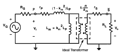
2. Also I have attached a model of a balun from IEEE paper. Is it possible in momentum to extract the values of lumped components ?

<a title="transformer_model.png" href="http://obrazki.elektroda.pl/7931295500_1411769686.png"><img src="http://obrazki.elektroda.pl/7931295500_1411769686_thumb.jpg" alt="transformer_model.png" /></a>

- - - Updated - - -

<a title="transformer_model.png" href="http://obrazki.elektroda.pl/7931295500_1411769686.png"><img src="http://obrazki.elektroda.pl/7931295500_1411769686_thumb.jpg" alt="transformer_model.png" /></a>

- - - Updated - - -

7931295500_1411769686.png
 

The shown model is in accordance with the transformer description in SPICE, L1, L2 and k, additionally winding resistances.

But which model representation do you want to map to it? Any example?
 

Hi Fvm,

I have an inductor model from a CMOS process foundry (runs in spectreRF). I want to represent the inductor using lumped components as shown in figure. How can I extract the equivalent values?

What do you mean by example of model representation? I dd not understand.
 

Status
Not open for further replies.

Part and Inventory Search

Welcome to EDABoard.com

Sponsor

Back
Top