Continue to Site

Welcome to EDAboard.com

Welcome to our site! EDAboard.com is an international Electronics Discussion Forum focused on EDA software, circuits, schematics, books, theory, papers, asic, pld, 8051, DSP, Network, RF, Analog Design, PCB, Service Manuals... and a whole lot more! To participate you need to register. Registration is free. Click here to register now.

Cosmo 4n35 optoisolator for DC voltage measuring

Status
Not open for further replies.

Iman12

Newbie level 6
Joined
Sep 27, 2010
Messages
14
Helped
0
Reputation
0
Reaction score
0
Trophy points
1,281
Activity points
1,391
Hi all,

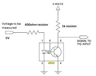
I've encountered a problem. I've tried to set the input current to the opto by using 5V and 600 ohm resistor, resulting less than 10mA input current. On the output side, I have put the voltage to 5V and resistor as 1k. It outputs fine, however, when I decrease the input voltage the output voltage increases. Is the opto reverse biased? Thanks all.
 

I can only guess at your circuit. I assume the phototransistor has a 1k collector load to 5V. So, when you reduce the input voltage the LED current will reduce so the collector voltage will increase because the voltage drop in the 1k will reduce due to the reduced collector current. If that doesn't make sense then maybe it will help to post your circuit,

Keith
 

Hi Keith, here is my circuit,

---------- Post added at 05:24 ---------- Previous post was at 05:24 ----------

72_1285622555.jpg
 

Yes, that is what I thought. In which case my description (which I guess didn't make sense!) is correct. If you reduce the input voltage the output voltage will increase. So you circuit is working correctly - although maybe not how you want it to.

Keith
 
  • Like
Reactions: Iman12

    Iman12

    Points: 2
    Helpful Answer Positive Rating
How do I improvised it to be directly proportional, Keith? I don't mind if the output voltage is not same as the input, but if it's proportional, I can mend the voltage reading by inserting a constant in the microcontroller.
 

I think someone should be looking up basic LED theory.
Not only does it invert but the LED will be completely inoperative at low voltage and the linearity graph will look like a cross section of the Himalayas.

Brian.
 

What you have will be inversely proportional which would be fine - it can be sorted out in software - except that if you were hoping to measure input voltage in that way you will fail because of the non-linear relationship between the LED current and voltage.

Keith
 

Hurm... I've thought so. At first I've wanted to use the isolated linear sensing, HCPL-7520. But it is quite expensive at 11usd per unit. I need to use 8 pieces lol. I guess there's no substitute for the hcpl-7520 eh? Is there any cheap optoisolator that you guys can recommend? Thanks

---------- Post added at 07:15 ---------- Previous post was at 06:19 ----------

Maybe I don't need precise output like 99% accuracy or something. But, if the manufacturer says that it can be used to isolate and whether it has a current transfer ratio of 60% or not, it should be able to at least measure it accurately up to a plausible value, don't it?
 

You can convert the input(voltage) to frequency and then you can use a opto for isolation. A simple 555 timer can convert the voltage to frequency is a cheaper alternate.

Nandhu
 
  • Like
Reactions: Iman12

    Iman12

    Points: 2
    Helpful Answer Positive Rating
I see. But I think it would be complicated as I would need 8 555 timer and 8 4n35 for my project. I think I will just let the ADC port get the signals directly from the contacts. It's just a prototype. The reason I wanted to put optoisolators because the project will interface with a 11kV switchgear. Stepped down to 5V of course! lol.
 

I see. But I think it would be complicated as I would need 8 555 timer and 8 4n35 for my project. I think I will just let the ADC port get the signals directly from the contacts. It's just a prototype. The reason I wanted to put optoisolators because the project will interface with a 11kV switchgear. Stepped down to 5V of course! lol.

If you feel 8 555timers and 4n35's too much, you can use one 555 timer and an opto and multiplex the input of 555timer. Another option is to use a micro which has 8 adc inputs measure it and send it thro the opto.
 

What voltage range are you trying to measure?

Keith

Keith, it is 5V

---------- Post added at 18:25 ---------- Previous post was at 18:23 ----------

If you feel 8 555timers and 4n35's too much, you can use one 555 timer and an opto and multiplex the input of 555timer. Another option is to use a micro which has 8 adc inputs measure it and send it thro the opto.

The opto that is intended to be used before the ADC at the microcontroller. Just wanted to protect the PIC from voltage spikes
 

You could add some circuitry to the LED side to turn your voltage into a current for the LED drive. I am not sure it would be much simpler than using a 555 to turn it into a pulse train though. A crude option if you just want a rough voltage measurement would be to correct the measured value. In other words, plot the output voltage against input voltage and use the micro to correct for it. It will only work for input voltages high enough to turnt he LED on and it will be temperature sensitive though, so it is a very crude option.

Keith.

Last time I tried to do it like that, and it works, but without the opto of course. Hehe. Anyways, I think I just try putting a voltage divider, try to make it to acceptable to say 10V and ratio it to got like 5V in the PIC (which the ADC pins can have a maximum of 5V). So if it is 10V in actual, it is actually 5V driven the ADC pins.

Why 10V? I just afraid with higher ratios the accuracy would deviate much further. Maybe, I should put the ratio of 30V to 5V? Voltage spikes normally takes form of 5-6 times the normal value. I don't know.. Need helpful comments guys~
 

If you have a high voltage available to drive the LED then the accuracy will improve although you will dissipate more power in the LED drive resistor.

It would be useful to know what you are trying to measure - where the source voltage comes from.

Keith.
 

If you have a high voltage available to drive the LED then the accuracy will improve although you will dissipate more power in the LED drive resistor.

It would be useful to know what you are trying to measure - where the source voltage comes from.

Keith.

I got 11kV on a switchgear then to 110V using potential transformer, and then 5V using a transducer. This is for voltage measurement.

For current, I got 800-1000A from the switchgear and then step it down using current transformer 800/1A. Then using a transducer I got about 14-20mA. Current measurement is by using current sense resistor.

Getting the source from medium voltage sources, it just made me afraid and wanted to use some isolation, even though voltage higher than 7V can already fry the pins on the PIC. It's an oxymoron altogether. But just following the norm, I wanted to use the opto. It is just that this time I try to reduce the cost by using other alternative than HCPL-7520, which I know found quite hard. Last time using HCPL-7520 and resolution of 1000 sampling per second, I can get accuracy of 0.1% at 200V but the accuracy tends to be lower at lower voltage say 30V = 8%. But then again, this can be improved by lowering the input voltage to be less than 100mV at the input of the HCPL.
 

Status
Not open for further replies.

Similar threads

Part and Inventory Search

Welcome to EDABoard.com

Sponsor

Back
Top