marko.severin
Newbie level 3

- Joined
- Mar 18, 2011
- Messages
- 3
- Helped
- 0
- Reputation
- 0
- Reaction score
- 0
- Trophy points
- 1,281
- Activity points
- 1,305
Hi guys,
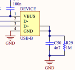
I'm getting a bit confused on how to correctly terminate connector shielding (like USB, D-SUB, or similar). For instance, most of the board I've seen uses the RC variant, like this one:

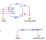
However, Texas Instruments uses a ferrite bead instead in one of their designs (Sitara Starterkit):

These are two completley different approaches. One shorts high frequencies to GND, the other blocks them. Which one is correct, or better said, when do I use one and when the other?
Thanks and best regards,
Marko
I'm getting a bit confused on how to correctly terminate connector shielding (like USB, D-SUB, or similar). For instance, most of the board I've seen uses the RC variant, like this one:

However, Texas Instruments uses a ferrite bead instead in one of their designs (Sitara Starterkit):

These are two completley different approaches. One shorts high frequencies to GND, the other blocks them. Which one is correct, or better said, when do I use one and when the other?
Thanks and best regards,
Marko
