Continue to Site

Welcome to EDAboard.com

Welcome to our site! EDAboard.com is an international Electronics Discussion Forum focused on EDA software, circuits, schematics, books, theory, papers, asic, pld, 8051, DSP, Network, RF, Analog Design, PCB, Service Manuals... and a whole lot more! To participate you need to register. Registration is free. Click here to register now.

convert PWM to analog waveforms for audio

Status
Not open for further replies.

pistole89

Junior Member level 3
Joined
Dec 9, 2010
Messages
29
Helped
0
Reputation
0
Reaction score
0
Trophy points
1,281
Activity points
1,570
Hello everyone,

I am confused to make Audio output amplifier for mono. I used LM386 amplifier.
The input of data comes from processor analog pin.
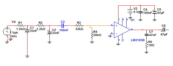
I show the image.

however, I do not really understand whether I need RC filter in the output amplifier.
Is there anyone have experience on this, please help me ?

How to make a correct and good audio output amplifier in detail?

Thanks for your help.
I will be really appreciate this. AudioOpAmp.png
 
Last edited:

Re: Audio Output amplifier design

The RC network on the amps output is called a Zobell network. As the audio frequencies rise beyond the audible, the impedance of a loudspeaker coil also rises. The impedance of the zobell network falls with frequency so the amplifier has a reasonable load on it through out its range where its gain exceeds unity. Leaving it out can give rise to ultrasonic oscillations.
Frank
 
Re: Audio Output amplifier design

Hi chuckey,

Thanks for your explanation.
However, I am still confused about the resistor 10 ohm placed on the output LM386.
What is the function of the resistor anyway ?

Thank you very much
 

Re: Audio Output amplifier design

At very high frequencies the ten ohms as the load for the amplifier because the impedance of the loudspeaker has risen to perhaps 100 ohsm.
Frank
 
Re: Audio Output amplifier design

Hi chuckey,

thank you very much

I have tried the circuit by giving square wave in the input.
However, I am also confused about the RC circuit before the LM318A Amplifier (actually LM386).
Is it a bandpass filter ? or Is it used to generate analog waveform ?

I have tried it using oscilloscope. the probe is connected in positive input of LM386
I attach the waveform in dutycycle.jpg

When I change the dutycycle of square wave, the waveform is shown in dutycycle_ubah.jpg

Could you please explain, how they works ?


Thank you very much.
Best regards,
 

Re: Audio Output amplifier design

What do you expect at the filter output when changing the duty cycle? Particularly with a square wave frequency far above the filter cut-off frequency. I won't expect much, apart from a magnitude change. It's hard to detect anything from your waveforms, because time base and attenuation both have been modified.
 
Re: Audio Output amplifier design

Hi

thanks.
I have attached the waveforms, when the attenuation and time base is the same with the same duty cycle.
I change the duty cycle from 0x00 to 0xFF and goes to 0x00 -0xFF again.

The duty cycle is based on the audio data from wave format.
The frequency of square wave is 44100Hz.
changing the duty cycle based on the data format is used to generate sound of music.

based on my software simulation, the cut off frequency is only about 1.5kHz


I need your help.

Thanks

Best Regards,
 

Re: Audio Output amplifier design

based on my software simulation, the cut off frequency is only about 1.5kHz
Yes, somethink like this. As you see, it's not a reasonable filter for a general audio amplifier. But where did you get the filter circuit? Why don't you simply refer to a LM386 datasheet example circuit?
How to make a correct and good audio output amplifier in detail?
Doesn't sound like a specification.
 

Re: Audio Output amplifier design

You can also try this design
https://www.kitsrus.com/pdf/k17.pdf

You have to consider that the capabilities of the specific chip are limited, the output power is limited and the distortion is on the high side.

Alex


Re: Audio Output amplifier design

Can you explain what you are trying to do because I don't think it is an audio amplifier.
Are you trying to do some kind of digital to analog using PWM?
Where is this square signal coming from and what do you want to do with it?

Alex
 
Re: Audio Output amplifier design

Hi,

Yes, I want to do digital to analog using PWM .
The square signal coming from microcontroller, where the duty cycle is based on digital data of wave.
The square signal is used to generate the sound to speaker.

I need helps.
Thanks.
 

Hi,

Is there anyone has experience to convert PWM from microcontroller into analog signal waveforms for audio ?
I need helps to understand the circuit
I have tried the circuit from
Development board Olimex SAM7-EX256 development for AT91SAM7X256 ARM7TDMI-S microcontroller


I also tested the wave form output, in + input amplifier LM318 in the picture (actually LM386)
When I send the same duty cycle


When I send duty cycle from 0x00-0xFF


Bodeplot from software, cut off frequency is about 1kHz


could anyone please explain how this circuit works?

Thanks

Best Regards,

Don't start new threads with the same content, it is not allowed.
I have updated the title of this thread and your posts are merged. [alexan_e]
 

Re: Audio Output amplifier design

Your previously have written about a processor analog output which turns out to be a PWM signal. That clarifies the purpose of the high frequent square wave and the low pass filter. If you intend an audio frequency range as it can be represented by a 44 kHz sample frequency, you would need a steeper lowpass than two cascaded first order RC filters.

Alternatively, you can feed the pwm signal to a push-pull switch and place a LC filter before the speaker to suppress the 44 kHz (class-D operation).
 
LM386 is a linear audio amplifier.....not like a class-d type audio amplifier which can be driven by a pwm.....you cant reproduce the exact audio with this......
 

LM386 is a linear audio amplifier.....not like a class-d type audio amplifier which can be driven by a pwm.....you cant reproduce the exact audio with this......
It's O.K. to drive it through a low pass.
 
Hi

Thanks for your answer.

If I have to make a steeper low pass filter. What is the recommended cut off frequency ?

Alternatively, you can feed the pwm signal to a push-pull switch and place a LC filter bef"ore the speaker to suppress the 44 kHz (class-D operation)."
Do you have an example of the circuit ?

Thanks2 a lot.

best regards
 

Hi

Is there any one could analyze more detail, how the circuit above works?
how they convert the PWM with duty cycle based on wave data into audio analog wave form ??

Please.. I really need your help..

Thanks.
 

What's your actual problem? Doesn't it work? Did you ever try to send an analog waveform? Up to now, I have only seen static values respectively DC voltages of different duty cycle. Just output 1 kHz sine *.wav data and watch the result.

If you have difficulties to understand general PWM operation, there's plenty of literature. Pulse-width modulation - Wikipedia, the free encyclopedia
 
Status
Not open for further replies.

Similar threads

Part and Inventory Search

Welcome to EDABoard.com

Sponsor

Back
Top