Continue to Site

Welcome to EDAboard.com

Welcome to our site! EDAboard.com is an international Electronics Discussion Forum focused on EDA software, circuits, schematics, books, theory, papers, asic, pld, 8051, DSP, Network, RF, Analog Design, PCB, Service Manuals... and a whole lot more! To participate you need to register. Registration is free. Click here to register now.

[SOLVED] [Control Theory] A question about the Frequency Response method

Status
Not open for further replies.

calenosa

Newbie level 5
Joined
Oct 1, 2009
Messages
10
Helped
0
Reputation
0
Reaction score
0
Trophy points
1,281
Activity points
1,363
From a Control Theory book I have:

"The frequency response function describes the steady-state response of a system to sinusoidal inputs. For a linear system, a sinusoidal input of a specific frequency results in an output that is also a sinusoid with the same frequency, but with a different amplitude and phase. The frequency-response function describes the amplitude change and phase shift as a function of frequency."

The above quotation is true, however, it doesn't say anything about the dc component in the steady-state response.

When I simulated the following system in MATLAB/Simulink:
model.png
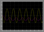
The source is a pure sine wave generator with no bias. I got the following response:
response.png

It can be seen that the response has a dc component, and I believe that the simulation result is correct. Therefore my question is can I calculate the dc component from the frequency response approach? If the answer is Yes, how can I do that?

Thank you.
 

Looks like the input signal (green) is \[-\sin(t)\]; therefore, the input angular frequency is \[\omega=1\text{rad/s}\].
Have you tried the Laplace transform method. The Laplace transform of the input \[-\sin(t)\] is \[-1/(s^2+1)\].
The Laplace transform of the output is the product of the input and system transforms.
\[
Y(s) = \frac{-1}{s^2+1} \, \frac{1}{s^2+s}=\frac{-1}{s(s+1)(s^2+1)}=\frac{A}{s}+\frac{B}{s+1}+\frac{Cs+D}{s^2+1}
\]
where A, B, C and D may be determined by partial fraction expansion. The time domain version of the output is of the form
\[
y(t) = A u(t) + B e^{-t} u(t)+ (\text{sinusoid \, at \, 1 rad/s}) \, u(t)
\]
so the output will definitely have a constant due to step magnitude A and and exponential decay B and a sinusoid. Does this make sense? Try for yourself and see if you can figure out the complete solution. But I agree, the solution that is simulated looks reasonable to me.

v_c
 
Last edited:

Hi v_c,

Thank you for your answer.

Well, The simulation result makes sense to me. My problem is that I don't understand the frequency response method thoroughly. I would like to know whether the frequency response method mentions the dc component of the output signal or not? If the answer is Yes, where can I find it (in the method)?
 

frequency response method will only give you the sinusoidal portion of the response -- not the constant plus exponential portions
 

You can put 0 for the frequency in transfer functions pertaining to frequency response. For example: 1/(1+i*w*R*C) is a transfer function for RC lowpass, if you put 0 for w, you will see its gain is 1 for DC inputs. The result you get looks strange, is that transfer function written for a real system?
 

Hi v_c,

I didn't read carefully about the scope of the frequency response method. This method only deals with stable systems, which means that it cannot be applied to the simulated system.

@ferdem: No, it is just an imaginary system.
 

In order to calculate the DC component, you can go to the differential equation and integrate it.
y/x = 1/(S²+S) ==> y'' + y' = x where x = [M*cos(wt)+k]*1(t)
1(t) is the step function.
We need to found the homogeneous and the particular integral then sum them toghther and compensate the pulses.

homogeneous: yh'' + y' = 0 the associated equation is then λ² + λ = 0 ==> λ1=0, λ2=-1 then:

yh = A1 + A2•exp(-t)

particular integral: is in the form yp =[B1*cos(wt) + B2*sin(wt) + B3*t]*1(t)

the general solution is y = yh + yp

solving and compensating the pulses (coming from the time derivative of 1(t)) it is possible to find the constants A1, A2, B1, B2 and B3. As far as I did correct calculations I found:

B1 = -M/(w²+1)
B2 = -M/[w(w²+1)]
A1 = -B2w - k - B1
A2 = B2w + k

thus:

y = M/(w²+1)*[-2+(1+k)*exp(-t) + cos(wt) + 1/w*sin(wt)]*1(t)
 

Status
Not open for further replies.

Part and Inventory Search

Welcome to EDABoard.com

Sponsor

Back
Top