Continue to Site

Welcome to EDAboard.com

Welcome to our site! EDAboard.com is an international Electronics Discussion Forum focused on EDA software, circuits, schematics, books, theory, papers, asic, pld, 8051, DSP, Network, RF, Analog Design, PCB, Service Manuals... and a whole lot more! To participate you need to register. Registration is free. Click here to register now.

[SOLVED] Control circuit for home brewing cabinet

Status
Not open for further replies.

KESV

Newbie level 5
Joined
Aug 26, 2015
Messages
9
Helped
0
Reputation
0
Reaction score
0
Trophy points
1
Location
Bergen, Norway
Activity points
84
Hi all,

I'm new to this forum and hope that you can help me.

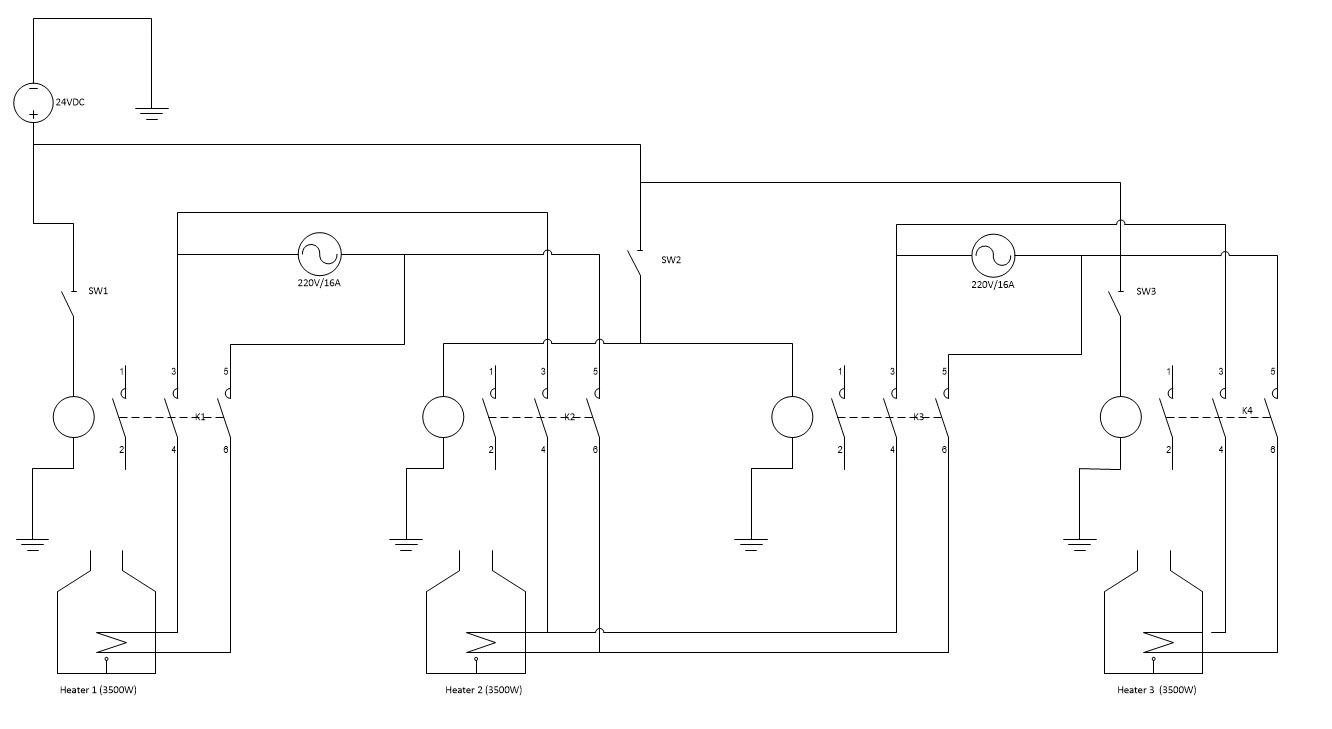
I'm in the process of building a control cabinet for my home brewery. The brewery consists of three heating elements (3500W) but I only have available two 16A power feeds (220V, living in Norway).
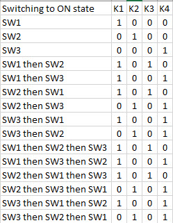
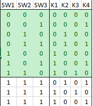
The heating elements are controlled by 3 switches (SW1, SW2, SW3) and 4 contactors (K1, K2, K3 and K4), where K1 is for heater 1, K2 & K3 are for Heater 2 and K4 is for heater 3. The three switches are on my drawing showed as NO, but can I can add more NC or NO to these.

I've created a logic on how this should work, with switching sequence in left column. The main areas of concern is that K1&K2 must never activate at the same time. This also applies to K2&K3 and K3&K4. All the contactor have additional 1xNO and 1xNC that can be used. If needed I can also add more relays. The control voltage for the contactors are 24VDC.

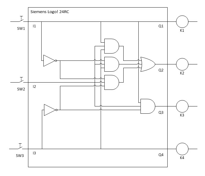
Attached is also a ladder diagram showing my thinking, but I'm stuck. No matter how hard I try I'm not able to solve this, it has been too long since my electronic exams.

Maybe not a very good description, but I hope it's understandable.
I'm very grateful for any help, my brewing of beer depends on this ;-)

Ladder diagram.jpgLogic.jpg
 

in your logic table , what does "SWx> SWy" indicates?

- - - Updated - - -

in your logic table , what does "SWx> SWy" indicates?

ok , it must be "both SWx and SWy are ON"(right?)
 

Sorry, that is clear for me but certaintly not a correct way of showing it.

ie. SW1>SW2 means that first I switch SW1 on, then SW2 on, so SW3>SW1>SW2 means first SW3 then SW1 then SW2.
My thoughts behind this is that if SW3>SW1 is switched on and then SW2 is switched on SW2 should have no effect. This is to protect against any wrong switching during brewing.

Hope that explained

- - - Updated - - -

Updated logic


Is there any specific reason why you chose to control heater 2 by two contactors and heater 1 and 3 by only one contactor? After you found out that the shown circuit is inavlid because it fails to implement the intended logic, you should probably drop this arbitrary assignment.

Other than suggested by the circuit, the intended logic seems to be completely symmetrical: Activate two heaters, block activation of a third heater as long as two are already activated. One should assume that the circuit somehow reflects this symmetry.

A practical question is about contactors, how many auxilary contacts have they available?

A symmetrical interlock could be implemented with three contactors having two N.C, auxilary contacts each. There's however a possible race condition, occuring if all three switches are activated simultaneously, or a switch is opened and closed too fastly with the other two switches already closed.
 

Hi, and thank you for you reply, I'll try to explain

Is there any specific reason why you chose to control heater 2 by two contactors and heater 1 and 3 by only one contactor?
The reasoning for this is the fact I should be able to use any combination of the three heaters on the two 220V/16A power supplies I have available. K2 and K3 receive each 220V and both are able to feed Heater 2 with power. In order to avoid short circuit between the two 220V I put in two contactors. If it could be done any easier it would be nice.


A practical question is about contactors, how many auxilary contacts have they available?
Each contactor have an auxillary NO and NC


I've attached the circuit diagram, maybe this explains more. Any suggestions to make it easier is welcome.
The bottom line is that I should be able to operate all three heaters using the three switches, making sure not overloading any of the two 220V's.


O.K., I understand about the double supply of heater 2. Are both supplies also from different phases? There's a specific situation where heater 2 has to be switched over from K2 to K3. If it involves switching to a different phase, a time relay would be required, similar to a wye-delta starter. The circuit can't be implemented with simple contactors only in this case.

A convenient way to implement the switching sequences would be a small programmable controller, e.g. a Siemens Logo device.
 

Thanks again for your reply.
The supply are from the same phase, but two breakers, and with european plugs I will never know which is the right way around in order to avoid short circuit.
I have considered a time relay, but still will not know how to create the logics for it to operate as intended.

Another thing is that the three switches can be extended with NO and NC switches, telemecanique - see www.goodluckbuy.com/xb2bd21c-no-2-p...t-selector-switch-replaces-telemecanique.html

Furthermore the switches are break before make, can that help?

When it comes to the other options you mention, yes I would look into a PLC if I started from fresh today, but all parts are purchased and the cabinet made ready.


As you say, same phase and unknown polarity isn't anything better. Break before make isn't enough. Expect an arc when opening a contactor which must be extinguished before closing the other circuit. Difficult to achieve without a time relays.

A Logo 230RC isn't more expensive and doesn't need more space than several auxilary contactors and one or more time relays.
 

A Logo 230RC isn't more expensive and doesn't need more space than several auxilary contactors and one or more time relays.

Thanks, I never even considered a PLC, it was meant to be a "simple" circuit. I realise know that this is not the case.

So, I've looked into the Siemens Logo PLC and like what I see, but it's not cheap, at least in Norway, about £140.
Reading about it I understand that I need the 24RC version, as my contactors are the same, and I do not want 230VAC in the switches on the panel door.

I downloaded the Logo software and have had a play around and solved most of the circuit, my only issue now is when all three switches are ON;

SW1+SW2=ON then SW3 should not be able to energize K4 when switched ON
SW1+SW3=ON then SW2 should not be able to energize K2&K3 when switched ON
SW2+SW3=ON then SW1 should not be able to energize K1 when switched ON

I've tried and tried, but no matter what I do something is wrong.

I've made a logic circuit diagram showing what I have done so far, hopefully it makes sentence.

Any help on this would be very much appreciated


I didn't read your previous schematic well regarding 24V supply. In this case 24V DC version is of course better.

Your logic design is purely combinational, so it must be expected not to handle the switch-over correctly. Simply adding a 100 millesond on-delay for K2 and K3 would help.

Of course it' still possible to implement the same logic with mechanical relays and time relays, if you prefer it.
 

I have not taken into account the on-delay as of yet, trying first to understand the logic. I will add time delay when all logics are ok.
It is the last three combination I struggle with now, do you please have any ideas on how to solve that?

Thanks again
 

I think it can't work as shown now.

Your original sequence description must implement an internal memory of previous state to know which switch has been activated last. This must be reflected in the logic circuit, it should either use some kind of feedback or an explicite memory element.
 

Hm, is that even possible with the Logo?

Thinking about it, it would have been soo much easier with a rotary switch...
 

Of course well possible with Logo or any other compact PLC.
 

Of course well possible with Logo or any other compact PLC.

After a steep learning curve on how to program a compact PLC, never done this before, I finally managed to get it to work using Siemens Logo8.
So thank you for directing me down the PLC way.

Next version of control cabinet will be planned with a PLC :thumbsup:
 

There are possible many other solutions. If it were me I would add another another breaker outside the panel and re-route.

Otherwise , if that doesn't work for you, I would insulate the pots and put in proportional temperature controllers with alternating complementary load shedding using 20A power $2Triacs. With full power it might take 20 minutes to reach full temp, but with added insulation it might only take 30 minutes to reach required temp.

then you can use full power on the 2nd breaker dedicated to 1 pot.

With a sealed lid an machine exhaust port you can vent mildew risk from high RH% in the house and prevent spillage.

Insulation is the key with solid state load shedding using any triac dimmer or temp controller or load shedding, with insulation, you can prevent breaker tripping.

Or you can bridge the Triacs to rotate 3 loads from 2 source Breakers B1,B2

B1 ---2---.---1---.---2---.---3---.---1.---.---2---....
B2 ---1---.---2---.---3---.---1---.---2--- .---3.---....

Then they get 66% of the power. and take 50% longer or more.

This is pretty simple logic to do.

In Winnipeg we had load shedding with outlets for 500 cars in the Parking lot for a 750W engine oil heater with 3 rows sharing a breaker sequentially. Perhaps you too are familiar with -30~-40'C
 

Status
Not open for further replies.

Similar threads

Part and Inventory Search

Welcome to EDABoard.com

Sponsor

Back
Top