Continue to Site

Welcome to EDAboard.com

Welcome to our site! EDAboard.com is an international Electronics Discussion Forum focused on EDA software, circuits, schematics, books, theory, papers, asic, pld, 8051, DSP, Network, RF, Analog Design, PCB, Service Manuals... and a whole lot more! To participate you need to register. Registration is free. Click here to register now.

Continous Sigma Delta ADC- Choosing the proper DAC

Status
Not open for further replies.
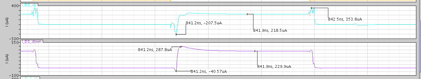
Unfortunately , i couldn't use the IDEAL switches.

Ideal switches from analogLib cause large spikes, at CLK transision , when the current should turn from zero to 350uA , it causes a spike about 2 or 3 mA .
So , even when using the IDEAL Switch , the total SNR is nearly the same.

I also tried designing the DAC with switches in SAT region , there is no luck too, SNR may have improved a few dB 's but still, not good.

I don't know what is the problem that i can't see, since that i am sure that Current Steering DAC could work with even higher frequencies than 384 MHz.
Any more help ??
 

I need help regarding SNDR.
My Bandwidth is 6 MHz , when i simulate using the maximum frequency , i got SNR =60 dB (for 0.5v differential input), However , when i tried to evaluate my SNDR, i tried with input frequency = 1.1MHz, the SNR (for the same input amplitude) became 36 dB !!!!

I don't know if it is an op amp linearity issue ? , issue related to C & R values i chose ? (although i tried changing the R & C keeping the same R*C value , and all are the same) ..
or what ??

I attached the semi-log output FFT if it helps.
The first is with the maximum frequency (5.8MHz) and the second is with 1.1MHz input signal.


Thanks ,
Shady
 

First, do you still have that resistor connected between the output of you DAC and the summation node? If so it should not be there. As for the SNDR dropping when having a smaller frequency, this is because you are not simulating enough. Also what type of window are you using hann? blackman-harris? Also, just wondering, since you said you simulated with ideal switches and still had a loss in performance, did you find out why... If you have this large spike of 3mA and its only like one ps, that ok for the ideal case.. Dont forget your clock cycle is like 2.6ns so a 1ps large spike is nothing. I don't know if you showed this before but can you post ideal spectrum left, built DAC right?

JGK
 

First, do you still have that resistor connected between the output of you DAC and the summation node?
JGK

No , that was for the resistive DAC i was trying to build earlier and for the IDEAL DAC i am using for modeling (resistive one). it is not there for the Current steering DAC.


As for the SNDR dropping when having a smaller frequency, this is because you are not simulating enough. Also what type of window are you using hann? blackman-harris?
JGK

I 'll try to simulate with more points, and i am using hamming window, do u have any advice about the window to use ?


Also, just wondering, since you said you simulated with ideal switches and still had a loss in performance, did you find out why... If you have this large spike of 3mA and its only like one ps, that ok for the ideal case.. Dont forget your clock cycle is like 2.6ns so a 1ps large spike is nothing
JGK

When i found out that large spike i just ignored the ideal switch , i thought that spikes like these are the ones i am trying hard to eliminate when designing the Real DAC. So, i just let the idea of modeling the DAC with ideal switches go.

Thanks for the reply.
 

ok, i have the semi-log plots for Vinput differential = 0.6 , i simulated with 4096 points.
Any ideas ?
Ideal DAC SNR= 78 dB , Current steering DAC SNR= 57.77 dB


Also, using the current steering DAC, there are some glitches,( refer to the next image). i believe they are one of the reasons of the SNR reduction. I designed the switches to operate in SAT region to decrease them as much as possible, also Rout is high (a few MegaOhms). Knowing that Ideally , the current should be equal 230uA .
Any idea how to resolve this issue?

 
Last edited:

Just wondering, if you copy paste the ideal spectrum onto the real DAC spectrum, does the NTF match out of band? It looks like it has changed but it could just be the scaling on the Y axis, could be another problem but just wondering.

Also, when you have the ideal spectrum, do you have current mirrors and ideal switches in your ideal DAC or is it verilogA or something. Also do you have noise on during your simulation? This could be afterall the thermal noise from your real DAC coming into play if your overdrives are not large to lower the thermal noise.

As for the switching, it seems that you are taking alot of time to switch and settle. How big are your switches and also how big are the drivers. Additionally, when you switch over from one side to the other side, or switching to dump, how does your current regulation in the current mirror change. Does it change at all?

As for running your switches in Saturation, its better to run them in triode and this can be seen when looking at monte carlo of the switching transistors, triode will have less effect, and since the drop over the switches should be small, this will result in you having more of an overdrive on the top and bottom transistors in the current mirror to decrease the noise. Also, just checking, are your current mirrors in saturation??


JGK
 

Status
Not open for further replies.

Part and Inventory Search

Welcome to EDABoard.com

Sponsor

Back
Top