Vermes
Advanced Member level 4
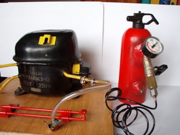
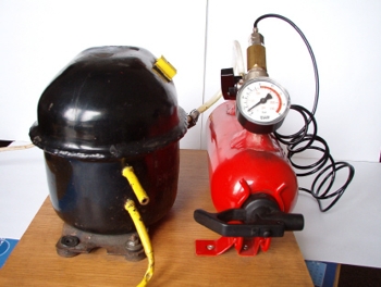
It is a home made airbrush compressor – a cheap and useful device. This compressor can be ued not only for painting models, but also for cleaning computers etc.
Elements used:
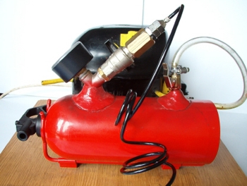
- piece of a plank 35x35cm
- old compressor of a fridge
- car fire extinguisher
- few reducers
- a small ball valve
- one-sided valve (valve from a car inner tube)
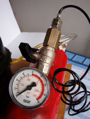
- manometer to 16 bars
- glue
- two nuts
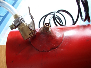
Mount the compressor and the handle of the extinguisher to the plank. To prepare the air cyllinder, weld nuts to the extinguisher. One of the nuts serves as one-sided valve. Apply a module with manometer and ball valve to the second one. After welding the nuts inside drill holes in the extinguisher. Put a valve from a car inner tube to one hole and glue them very accurate. The second hole should be filled with a module of manometer module and ball valve. Airbrush would be connected to that point. Fridge compressor should be connected with the tank by a short hose, previously stengthened with bands, so air does not go outside. After that, test the compressor's strength.
Pictures:

Link to original thread (useful attachment) – Budowa sprężarki do aerografu.