Continue to Site

Welcome to EDAboard.com

Welcome to our site! EDAboard.com is an international Electronics Discussion Forum focused on EDA software, circuits, schematics, books, theory, papers, asic, pld, 8051, DSP, Network, RF, Analog Design, PCB, Service Manuals... and a whole lot more! To participate you need to register. Registration is free. Click here to register now.

Connecting MicroController to GSM modem via RS232

Status
Not open for further replies.
Although GSM modem average current is below 1A, peak current will be about 2A, so it can't be supplied by a 1A voltage regulator without a sufficient buffer capacitor. This can be a simple explanation for the observed behaviour, if the reset occurs after entering the SIM pin code and in turn the modem starting to connect the base station. Otherwise, the modem may have been damaged by previuosly applied overvoltage.
 
@ ckshivaram
I have checked the SIM card connections, they are not shorted.

@ FvM
can you please suggest any other voltage regulator that can supply, 4.5V and 2A.

One more thing to say,
Some times its fully working, even i sent sms and make calls. But this is a very rear case.
I mean if i restart the supply again and again , and then may be some time it may fully functioning, and not reset.

And if i unplug the supply and connect again, its in previous state.

It means the modem is not damage because some times it works. Am i right?
 

regulator for 2A is not required as modems use either 5V regulator or they use LM317. there should be some reset problem , check the capacitor associated with the input to the regulator in the modem. Modem is not damaged.
 
You don't necessarily need a stronger voltage regulator, just a buffer capacitor directly at the gsm modem, e.g. 1000 uF. There's however a number of 2A capable voltage regulators available, e.g. ST L78S05. For a first test, you can also connect two 7805 in parallel.
 
OK,

Now i solved the restarting problem by Inserting two 7805 Voltage regulators in parallel and 100 uF capacitor as a buffer.

Thank you guys (Specially FvM and ckshivaram )for all the help regarding power issues.

Now i am trying to access my SIM tool kit to perform some specific operations like access menus, display menu items, select menu item and inpput text in text fields, etc etc.

I am using sim300 and SIM300W for this task.

Can any body help me to do so?

I have tried some Commands Already but i think i make some format mistakes.
Here are the commands:

AT+STGR
AT+STK
AT+STSF

and alot more. but for all it gives an error
 

No one on the board knows about the Sim application ToolKit operations.....
Strange...
 

can i also, need help... for my testing of my gsm modem 900d... please some one help me....
 

dear sir pls help me out in connecting my gsm module to the Arduino AT328..
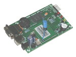
this is my GSM modem and its details..
GSMModemUSB_LRG.JPG

This is a plug and play GSM Modem with a simple to implement RS232, TTL Serial and USB interface. Use it to send SMS, make and receive calls, and do other GSM operations by simple AT commands through a serial interface from microcontrollers and computers. It uses the highly popular SIM300 module for all its GSM operations. It comes with a standard RS232 interface which can be used to easily interface the modem to microcontrollers and computers. The modem also features a serial TTL interface option. When plugged onto a USB port, the board shows up as a virtual serial port on the computer. All modem operations(sending and receiving messages, calls, etc) can be carried out by sending AT commands to this virtual serial port though a serial terminal program. Most programming languages allow sending and receiving serial commands to a serial port and can be used to write softwares that can operate the modem without the need to implement any complex USB interface. This makes the modem a great choice if you plan to use GSM features on a computer.

The modem consists of all the external circuit required to start experimenting with the SIM300 module like the power regulation, antenna, SIM Card connection, etc.

Features

Uses the extremely popular SIM300 GSM module
USB interface for easy interface to computers
Provides the industry standard serial RS232 interface for easy connection to computers and other devices
Provides serial TTL interface for easy and direct interface to microcontrollers
Power, RING and Network LEDs for easy debugging
Onboard buzzer for general audio indication
Onboard 3V Lithium Battery holder with appropriate circuitry for providing backup for the modules’ internal RTC
Can be used for GSM based Voice communications, Data/Fax, SMS,GPRS and TCP/IP stack
Can be controlled through standard AT commands
Module’s operation mode can be controlled through the PWR Switch connected to the PWR pin (refer the SIM300 datasheet for more information)
Comes with an onboard wire antenna for better reception. Board provides an option for adding an external antenna through an SMA connector
The SIM300 allows an adjustable serial baudrate from 1200 to 115200 bps (9600 default)
Modem a low power consumption of 0.25 A during normal operations and around 1 A during transmission
Operating Voltage: 7 – 15V AC or DC (board has onboard rectifier)


Note: The modem consumes current of nearly 1A during transmission, please make sure that your power supply can handle such currents.
 

Dear sir,
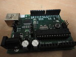
my quest is whether i need a max 232 for my arduino
DSC00467.JPG

pls help me sir
 

hi

i am facing the same problem of sending the sms from Microcontroller(atmega8515) through sim300 module

i have tested my gsm module using pc its working fine,and through controller also i have checked its working fine, but wen i interfaeced controller with sim300 there is no response...here is my code iam using avrstudio5


#include <avr/io.h>

#include <string.h>
unsigned int i=0;
char enter=0x0A;
char ctrZ=0x1A;

void USARTInit()
{
UBRRH = 0x00;
UBRRL = 0x0C;
UCSRC = (1<<URSEL)|(1<<USBS)|(1<<UCSZ1)|(1<<UCSZ0);
UCSRB= (1<<RXEN)|(1<<TXEN);
UCSRA = (1<<U2X);
}

char get_char()
{

while(!(UCSRA & (1<<RXC)))
{
}
return UDR;
}

void put_char(char data)
{

while(!(UCSRA & (1<<UDRE)))
{
}


UDR=data;
}

void put_str(char *str, int len)
{


for(int i=0;i<len;i++)
{

UDR=str;

while(!(UCSRA & (1<<UDRE)));

}
}

int main (void)
{

USARTInit();

put_str("AT",3);
put_char(enter);

while(get_char()!='O');
while(get_char()!='K');

put_str (" AT+CMGF=1",10);
put_char(enter);

while(get_char()!='O');
while(get_char()!='K');

put_str (" AT+CMGS=\"ph no \"",21);
put_char(enter);

put_str(" hi",4);
put_char(ctrZ);

}


where i am going wrong i dont know
plz help me in this aspect


thanks in advance
 

Hi friends,
I connect My micro via RS232 and MAx232 to PC and watch the result in the hyper terminal.
But when i connect my serial port to GSM Modem,the modem does not respond to AT commands...
I think modem not receives any at command...
thanks for your help.

hi mpch_elec,

I have worked on interfacing between SIM300 GSM modem & LPC21xx controller & it works well.
Few points tobe taken care
1. Modem has inbuilt max232, so how about uC side.
2. Try connecting straight cable(RS232) between Modem & uC (b'coz i tried with cross cable it was no responding).
3. Try interchanging Tx & Rx pins.

which controller you are using ?

---------- Post added at 17:49 ---------- Previous post was at 17:39 ----------

hi

i am facing the same problem of sending the sms from Microcontroller(atmega8515) through sim300 module

i have tested my gsm module using pc its working fine,and through controller also i have checked its working fine, but wen i interfaeced controller with sim300 there is no response...here is my code iam using avrstudio5


#include <avr/io.h>

#include <string.h>
unsigned int i=0;
char enter=0x0A;
char ctrZ=0x1A;

void USARTInit()
{
UBRRH = 0x00;
UBRRL = 0x0C;
UCSRC = (1<<URSEL)|(1<<USBS)|(1<<UCSZ1)|(1<<UCSZ0);
UCSRB= (1<<RXEN)|(1<<TXEN);
UCSRA = (1<<U2X);
}

char get_char()
{

while(!(UCSRA & (1<<RXC)))
{
}
return UDR;
}

void put_char(char data)
{

while(!(UCSRA & (1<<UDRE)))
{
}


UDR=data;
}

void put_str(char *str, int len)
{


for(int i=0;i<len;i++)
{

UDR=str;

while(!(UCSRA & (1<<UDRE)));

}
}

int main (void)
{

USARTInit();

put_str("AT",3);
put_char(enter);

while(get_char()!='O');
while(get_char()!='K');

put_str (" AT+CMGF=1",10);
put_char(enter);

while(get_char()!='O');
while(get_char()!='K');

put_str (" AT+CMGS=\"ph no \"",21);
put_char(enter);

put_str(" hi",4);
put_char(ctrZ);

}


where i am going wrong i dont know
plz help me in this aspect


thanks in advance


hi kumar97,

Code looks proper, check the hardware connection(Tx, Rx, Gnd), baudrate.
 

there are many video tutorial also. you can check them too
 

Status
Not open for further replies.

Similar threads

Part and Inventory Search

Welcome to EDABoard.com

Sponsor

Back
Top