Continue to Site

Welcome to EDAboard.com

Welcome to our site! EDAboard.com is an international Electronics Discussion Forum focused on EDA software, circuits, schematics, books, theory, papers, asic, pld, 8051, DSP, Network, RF, Analog Design, PCB, Service Manuals... and a whole lot more! To participate you need to register. Registration is free. Click here to register now.

Connecting 1/4" jacks?

Status
Not open for further replies.

Xorophone

Newbie level 5
Joined
Oct 6, 2015
Messages
8
Helped
0
Reputation
0
Reaction score
0
Trophy points
1
Activity points
75
I'm very new to electronics and now I'm trying to learn about circuit diagrams, but I have a problem.

I'm trying to build the circuit under "Step 1: The High Pass Filter" on the link below, but I don't know how to connect my 6.35mm (1/4") jacks to the circuit. I want to connect mono jacks to the input and output. What confuses me the most is the ground wire, but I need help with the rest too. I'm guessing I'm somehow supposed to connect a wire between the output and input, but which pin on the jacks do I use and why? How do I connect the jacks to the input and output wires?

Here's the link:
https://www.instructables.com/id/Passive-Filter-Circuits/

As a bonus question; Is it possible to connect a potentiometer to the circuit to control the cutoff point? If so, how and where do I connect it? Which type of potentiometer should I use?

Please try to use simple words to describe what you mean, because as you may have noticed I'm very inexperienced and having english as my second language doesn't make it easier either.

I'm thankful for any help I can get!
 

The circuits are more symbolic than practical. There are actually two ground connections which are joined together. On your jacks you will find two screw or solder tags, one goes to the sleeve and one to the tip of the jack. The sleeve is the ground side so you need to wire both of them to the ground point on the board, essentially linking them together through the wiring and also connecting to the capacitor on the board. The input goes to the tip connection on one jack and the output goes to the tip on the other.

The normal way of wiring a jack is to use a screened cable, that is a cable with a center wire, an insulated layer around it and an outer woven wire braid (known as co-axial cable). The idea is the braid forms an interference shield around the inner wire. The inner wire would be the connection to the jack tip and the braid would be wired to the jack sleeve. It will work if you just use two wires but you risk picking up interference, particularly low frequency 'hum' when you don't use the screen method.

If you want to experiment with different cut-off frequencies you can either change the capacitor value or the resistor value. Large value variable capacitors are physically big and very expensive but variable resistors are cheap and easy to get hold of. I suggest you get hold of a potentiometer with a value of say 10K Ohms and preferably with a linear track. Where the resistor is in the circuit, wire to one end of the potentiometer and the wiper (usually center pin) of the potentiometer. As you turn it the value will change from zero to full resistance. Note that you can get two types of potentiometer, linear and logarithmic, they both do the same job but the way the value changes at different rotation angles is different. For your application, a linear type will work best.

If you swap the positions of the capcitor and resistor it will work in reverse, instead of being a high-pass filter it will be a low-pass filter. Be aware that in a simple circuit like that the effect will be noticable but not dramatic, the rate the volume falls beyond the cut-off frequency will be very gradual and the overall volume will change as well. It will work more like a selective volume control than a tone control.

Brian.

Thank you so much for the help!

Can you please explain the sleeved wire method more in-depth? I think I get the basic idea, but I still don't understand what you mean.
What should I wire to the wiper on the potentiometer and what do I do with the other two connections?
Do you know of any other high- and lowpass filters that will work better? I'm planning on building a granular synth (From the Notes and Volts Youtube channel) and I want to add a filter as another module. How can I create a normal Low, Mid, High filter and is it possible to add a resonance knob to the high- and lowpass filters?

Sorry if I'm asking too many questions!
 

These filters are so simple that they does not do much for audio except to gradually reduce low frequencies and high frequencies. If you connect in series a lowpass and a highpass then the very simple resulting bandpass filter has poor performance.
 
These filters are so simple that they does not do much for audio except to gradually reduce low frequencies and high frequencies. If you connect in series a lowpass and a highpass then the very simple resulting bandpass filter has poor performance.

Do you know about any other circuit diagrams/tutorials that will work better for me? A resonance knob would be great too. For some reason I've had a hard time finding it. As I said in the previous post it would be great if you could show me how to make a filter that controls the low, mid, high frequencies like on an amplifier.
 

Can you please explain the sleeved wire method more in-depth? I think I get the basic idea, but I still don't understand what you mean.
What should I wire to the wiper on the potentiometer and what do I do with the other two connections?
Do you know of any other high- and lowpass filters that will work better? I'm planning on building a granular synth (From the Notes and Volts Youtube channel) and I want to add a filter as another module. How can I create a normal Low, Mid, High filter and is it possible to add a resonance knob to the high- and lowpass filters?

Sorry if I'm asking too many questions!

Sleeved wire is the normal method of wiring almost all signal cables, you almost certainly have it on microphones, all your audio patch leads and maybe headphones. It's nothing more than an inner wire surounded by a braided or 'twisted around' screen. As you normally need two connections (per channel) to carry audio, the signal and the ground, it makes sense to use the screen as the ground connection. In some 'pro' studio equipment it's done a little differently, there are two signal wires inside the screen and they carry differential signals but 99.9% of consumer equipment uses standard single screened cable. Technically it is called co-axial cable, meaning "on a common axis" but it is also known as "screened audio cable". For stereo applications you often see two individual screened cables with their plastic outer covers bonded together for convenience of handling. If you look at a cut cable 'end on' it's outline looks like the shape '8' so it sometimes gets called 'figure 8 profile' cable.

As Audioguru and I pointed out, the simple single stage RC filter has lots of deficiencies, if can only remove the frequencies you don't want, it can't boost the ones you want to keep. For example a 'high pass' filter works by progressively lowering the low frequencies. As they do not have a sharp cut-off frequency, they inevitably also reduce someof the frequencies you are trying to keep. The better way to do it is to amplify the signal and put the RC filter in the amplifiers negative feedback loop. Negative feedback reduces the gain of an amplifier so instead of directly filtering the audio, you apply a frequency dependant control of the amount you amplify it. Low pass and high pass filters work the same way, you just reverse the components that decide the gain, mid-pass (band pass) filters are a combination of high and low pass with a gap between their cut-off points. Unfortunately, there is a big step in the technology you need, you are forced into using transistor or integrated circuit amplifiying stages and considerably more than just two components. Try the present design first and see how you get on before jumping to 'high tech'!

The potentiometer is to replace the resistor in the original design. A normal resistor is a length of partially conducting material with a connection at each end, the length and conductivity of the material decide it's value. A potentiometer (like a volume control) is specially constructed so it not only has the usual two ends but a movable wiper that can traverse from one end to the other. For example, when used as a volume control you ground (no signal) one end, put the full signal level at the other and take the output from the wiper. At each position along the way from one end to the other it 'taps' into a different amount of signal level, hence the volume you hear. Moving the wiper toward the ground end lowers the volume and toward the signal end takes it nearer to full volume. The partially conductive material is normally carbon based and can be a straight 'track' in a slider control or curved in a rotary control. If you ignore one end of the potentiometer and make connection to the other end and the wiper, you get a resistor with a value proportional to the length of track between them - a variable resistor!

Brian.

Wow, thank you so much! I think I'm getting a better understanding now, but I'll experiment a bit and do some more researching.

This question may not really be relevant to this thread, but I don't want to make a new thread for every question. Is there any way I can replace potentiometers with 1/4" jacks (or something similar) and then be able to control them using potentiometers, LFO's or something similar on another module?
 

I'm not clear what you mean but if you are asking if the resistor, fixed value or variable using a potentiometer, can be remotely placed elsewhere and connected by cable and jacks, yes you can. The physical location of the components is unimportant but extra wiring length increases the risk of interference being picked up.

Brian.

If you look at a modular synthesizer for example, you use wires to make certain things modulate other things, if you know what I mean. So if I for example build a filter, I want to replace all of the potentiometers with jacks, to be able to modulate the value using external controllers of some sort (I'm talking about changing the resistance value of the variable resistor, not MIDI signals). I'm not talking about permanent wiring, I want to be able to choose what I want to connect the variable resistors to after the filter module has been soldered and assembled.

Is it possible to do with 1/4" jacks or do I need something else? How can wire it to make it work? I'm guessing I need to add some more components, because a 1/4" jack can't do this by itself, right?
 

Do you know about any other circuit diagrams/tutorials that will work better for me? A resonance knob would be great too. For some reason I've had a hard time finding it. As I said in the previous post it would be great if you could show me how to make a filter that controls the low, mid, high frequencies like on an amplifier.
Here is a standard tone controls circuit that can boost or cut low, mid and high frequencies. The pots adjust how much boost or cut but the frequencies are fixed.

A filter boosts or cuts low, mid or high frequencies. A filter does not resonate, an oscillator resonates.
 

Attachments

  • Baxandall tone controls3.PNG
    Baxandall tone controls3.PNG
    17.1 KB · Views: 58
  • Baxandall tone controls3 graph.PNG
    Baxandall tone controls3 graph.PNG
    28.7 KB · Views: 57
Here is a standard tone controls circuit that can boost or cut low, mid and high frequencies. The pots adjust how much boost or cut but the frequencies are fixed.

A filter boosts or cuts low, mid or high frequencies. A filter does not resonate, an oscillator resonates.

Did you forget to add the picture? I can't seem to find it.

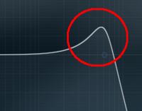
Maybe resonance when it comes to electronics isn't the same thing as when it comes to music, but the part inside the red circle, on the picture below, is what I mean. The resonance knob basically changes how high that peak goes. This of course only works with lowcut and highcut filters.


- - - Updated - - -

I can see your pictures now. Thank you for the circuit diagram, I will take a look at it and try to develop an understanding. Just one question, what are those big IC1 and IC2 arrow-things?
 
Last edited:

Those are the amplifier stages I mentioned a few posts back. The right side of the triangle is the amplifier output, the pin marked '-' is called the 'inverting input' and the '+' is called the 'non-inverting input'. Basically, the inputs work the same except the '-' turns the signal upside downwhile the '+' doesn't.

I mentioned that more complex filters use feedback to control the gain at different frequencies and negative feedback reduces gain. You get negative feedback by coupling some of the amplifier output back to it's '-' input and if you look closely, you will see a variation of the RC filter you started with in the feedback path.

The simple Baxendall (name of it's inventor) tone control gives bass lift and loss and treble lift and loss but it can not change the frequencies it starts to work at.

Brian.

Oh, I understand! I guess you mean the phase gets inverted. Being able to change which frequencies the filter will affect isn't that important for me. I just want a simple filter to quickly be able to change the sound slightly. Sorry for reposting, but what do you think about this:

If you look at a modular synthesizer for example, you use wires to make certain things modulate other things, if you know what I mean. So if I for example build a filter, I want to replace all of the potentiometers with jacks, to be able to modulate the value using external controllers of some sort (I'm talking about changing the resistance value of the variable resistor, not MIDI signals). I'm not talking about permanent wiring, I want to be able to choose what I want to connect the variable resistors to after the filter module has been soldered and assembled.

Is it possible to do with 1/4" jacks or do I need something else? How can wire it to make it work? I'm guessing I need to add some more components, because a 1/4" jack can't do this by itself, right?
 

You need to learn about the basics of electronic circuits.
You show a lowpass filter with a sharp cutoff of high frequencies and it has a high Q at its cutoff frequency that causes it to peak.
Here is a Sallen and Key third-order lowpass filter with a low Q and a high Q. I changed one resistor value to cause it to peak. If It peaks more then it will be an oscillator.
 

Attachments

  • 3rd order lowpass filter.png
    3rd order lowpass filter.png
    39.7 KB · Views: 60

Status
Not open for further replies.

Part and Inventory Search

Welcome to EDABoard.com

Sponsor

Back
Top