Continue to Site

Welcome to EDAboard.com

Welcome to our site! EDAboard.com is an international Electronics Discussion Forum focused on EDA software, circuits, schematics, books, theory, papers, asic, pld, 8051, DSP, Network, RF, Analog Design, PCB, Service Manuals... and a whole lot more! To participate you need to register. Registration is free. Click here to register now.

[SOLVED] Confusion with Differential Amplifier.

Status
Not open for further replies.

Shayaan_Mustafa

Full Member level 5
Joined
Jan 16, 2011
Messages
267
Helped
0
Reputation
0
Reaction score
0
Trophy points
1,296
Activity points
3,213
Hello experts!

I hope all of you will be fine.

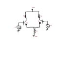
Here is image.
Untitled.jpg

As you can see, it is the differential amplifier i.e. the first circuit of the Opamp.
We know for differential amplifier we choose transistors to be identical with all respects. So their emitter are also common and share one resistor RE as shown in figure.

Why don't we do this with collector? We know R1 and R2 should be identical so why don't collector one resistor rather two?

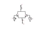
In short, why the circuit should not look like this,
Untitled1.jpg
 

Hi shayaan
Did you understand how a differential amplifier does work really ? collectors are out puts ! differential amplifier will have many advantages . such as ability of driving float loads . and of course removing noises . but in your second circuit with a common RC all of the advantages are destroyed !
Best Wishes
Goldsmith
 
Hi Mustafa,

remember the working principle of a differential amplifier: When Ic1 (first transistor) increases by - for example - 20% the current Ic2 (second transistor) goes down by 20%.
Now ask yourself, what the voltage variation across Rc will be.
It's clear now?
 
In the first circuit, the output voltage is Vout = Vc,q1 - Vc,q2. So what's the output voltage of the second circuit?
 

@goldsmith

Did you understand how a differential amplifier does work really ?
Yes sir! I know but I am confuse if both have same characteristics even with common RE the why not common RC.

collectors are out puts ! differential amplifier will have many advantages . such as ability of driving float loads . and of course removing noises .
It is really good point in your reply. I don't know what are the advantages of differential amplifier. But you made it. I appreciate.

but in your second circuit with a common RC all of the advantages are destroyed !
I know my second circuit is wrong. But can you explain how these advantages are destroyed?

@LuW

Hi Mustafa,

remember the working principle of a differential amplifier: When Ic1 (first transistor) increases by - for example - 20% the current Ic2 (second transistor) goes down by 20%.
Now ask yourself, what the voltage variation across Rc will be.
It's clear now?
It is good point to think why my 2nd circuit is wrong. But can you define qualitatively? If I use my 2nd circuit will my load get destroyed?

@FvM

In the first circuit, the output voltage is Vout = Vc,q1 - Vc,q2. So what's the output voltage of the second circuit?
I am confuse with your reply :-(
 

Quotation: It is good point to think why my 2nd circuit is wrong. But can you define qualitatively? If I use my 2nd circuit will my load get destroyed?

Mustafa, your circuit is not "wrong". For my opinion, a circuit never can be "wrong".
It only can work as desired - or not. To answer your question: No, it will not be destroyed.
However, your second circuit is not an amplifier that is able to amplify voltage differences (which is the task of a differential amplifier.)
As I have told you in my first reply, the current fluctuations through the common Rc cancel each other. As a result, there will be no output voltage resulting from an input difference.
To understand this you should try to become familiar with the principle of the classical diff. amplifier configuration.
 
Hi shayaan
Sorry because of an improper word of "Destroy " . i shouldn't use that ! LvW is quite right . i didn't think about this sentence that " a circuit never can be wrong " . and it is my first time to hear this sentence . and it seems pretty reasonable . and in my opinion it is a beautiful believe for each circuit ! it means your circuit ( second one ) is not a differential amplifier which can amplify AV*(VA-VB) . again sorry if my words were not good .
Best Wishes
Goldsmith
 
Your second circuit would be a good circuit to handle larger currents, current division through your transistors. That is when you make the two inputs common.

\[I_{C1} = I_{C2} = \frac{I_{C,single-transistor}}{2}\]

Thus, half the current. But it is not a diff-amp.
 

Hi Baas Rietrot
Larger currents ? if yes why not using two transistors in parallel and two balance resistors ? why that arrangement ?
Best Regards
Goldsmith
 

His second circuit is almost two transistors in parallel, the inputs is not common in the figure.
 

If you want to sense near ground you would invert the components and use a proper current source on the emitter rather than a Rs series resistor. You would want to use one of the collectors as an output .


For example on this LM358 Op Amp.
Screen shot 2012-07-24 at 5.14.20 PM.png

Here they improve the design with a current mirror diode arrangement in the lower collectors so they split the current source in the emitter.

If you wanted a differential output.. your suggestion would be fine if you had two Collector resistors. but for cascading stages controlled currents are better than fixed resistors where the bias voltage changes with Vbe and temperature.

Your second design allows either input to pull down the collector, so it becomes a mixer circuit with differential input and multiplying them to the collector.
 
Last edited:

His second circuit is almost two transistors in parallel, the inputs is not common in the figure.
He has two input signals !

- - - Updated - - -

By the way he has not any balance resistor !
 
Post#12 clarifies somehow good to me. So I think I have understood.

Thank you all, especially, Goldsmith and LuW.
 

Status
Not open for further replies.

Similar threads

Part and Inventory Search

Welcome to EDABoard.com

Sponsor

Back
Top