ANS HAFEEZ
Advanced Member level 4
- Joined
- Jul 25, 2013
- Messages
- 101
- Helped
- 5
- Reputation
- 10
- Reaction score
- 5
- Trophy points
- 1,298
- Location
- LAHORE,PAKISTAN
- Activity points
- 1,911
Follow along with the video below to see how to install our site as a web app on your home screen.
Note: This feature may not be available in some browsers.

")
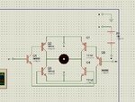
I see no schematic for your corrected circuit.
Why did you use the extremely slow 1N4007 mains rectifier instead of a fast diode.
Good for you, I was wrong.No no its NOT 1N4007 ITs "UF" 4007
I don't see any significant advantage for using Schottky diodes for the reverse biased protection diodes across the transistors. They only conduct for a short period of time when the bridge turns off due to any load inductance and the diode forward drop for that has an insignificant effect on circuit operation.........................
If you have them in stock, use schottky diodes. This is not because of the speed of UF4007, but because of forward voltage drop. ............................
.......................
Okay. But I don't see how the reverse Hfe affects what type of CE protection diodes are needed. :?: The transistors are never significantly turned on in the reverse direction, even with standard Si junction protection diodes.@crutschow: This would be true for MOSFET, but he uses BJT, and BJTs have low HFE in reverse direction as far as I know.
Okay. But I don't see how the reverse Hfe affects what type of CE protection diodes are needed. :?: The transistors are never significantly turned on in the reverse direction, even with standard Si junction protection diodes.
i am using 12v motor with maxiimum currunt of 0.5A and use the resistors of 1 watt
and i didnt get my answer right now ???
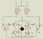
BJT's do not conduct well in there reverse direction so curent goes through the protection/freewheel diodes, even when the BJTs are turned on.
When the motor current goes from left to right and you turn-on Q2 (right-up) and Q3 (left-down), the current must go via the freewheel/protection diodes (because of motor inductance, or some series inductance for EMI reduction). So when having a good selection of inductance and switching frequency, the diodes conduct during a significant time and then schottky rectifiers reduce the dissipation.
- - - Updated - - -
What do you mean with "maximum" current of 0.5A?
What type of load do you have and how fast would like to accelerate that load, as that determines the value and the duration of the inrush current. When you don't know, try to measure the inrush current of the motor with load when applying 12 DC to it from a large power supply. You need an real time sampling oscilloscope for that and a small resistor for measuring current (via voltage measurement across the small series resistor).