Continue to Site

Welcome to EDAboard.com

Welcome to our site! EDAboard.com is an international Electronics Discussion Forum focused on EDA software, circuits, schematics, books, theory, papers, asic, pld, 8051, DSP, Network, RF, Analog Design, PCB, Service Manuals... and a whole lot more! To participate you need to register. Registration is free. Click here to register now.

Confusing op amp circuit

Status
Not open for further replies.

anindya

Newbie level 4
Newbie level 4
Joined
Jun 21, 2010
Messages
7
Helped
0
Reputation
0
Reaction score
0
Trophy points
1,281
Location
india
Visit site
Activity points
1,341
Can anyone please explain the working of the circuit

It seems it uses negative feedback
 

It's a voltage regulator. It uses negative feedback from the output to adjust the pass transistor to keep the output voltage at the adjusted value, independent of the load current.

To see its operation, assume there is a slight drop in output voltage. Follow that change in voltage through the circuitry to see which voltages to up and which go down (ignore the magnitudes), and how that affects the output voltage.
 

i understand that it is a voltage regulator ..the circuit does not work if you reverse the polarity/swap the pins..question is how exactly do you find out in circuits like this whether it is a positive feedback/negative feedback ? if some one can throw some light on the issue of negative feedback on the positive terminal of the opamp..it would be helpful
 

Seems like there's a hundred different voltage/current regulator configurations. We can't be expected to keep every one of them fresh in our memory.

At times like this a simulator is invaluable. Particularly an animated interactive one.

The upper transistor is oriented in the customary position of a pass transistor. However the rest of its operation is not easy to grasp.

This is one of those schematics that it might help if you re-draw it.

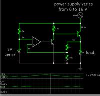
It is redrawn as shown in this screenshot:


To observe it as animation, click the link below. It will open the website www.falstad.com/circuit.

It will load the schematic, and run it on your computer. (Click Allow to load the Java applet.)

https://tinyurl.com/cmjwllu

You can change values by right-clicking a component and selecting Edit. This will bring up an edit window.
 

? if some one can throw some light on the issue of negative feedback on the positive terminal of the opamp..it would be helpful

The lower transistor (original drawing!) - together with the resistor - operates in common emitter configuration. Thus, there is a phase inversion between its base (opamp output) and the base of the path transistor.
This phase inversion provides negative feedback (and requires a non-inverting opamp).
 

i understand that it is a voltage regulator ..the circuit does not work if you reverse the polarity/swap the pins..question is how exactly do you find out in circuits like this whether it is a positive feedback/negative feedback ? if some one can throw some light on the issue of negative feedback on the positive terminal of the opamp..it would be helpful
It isn't just the polarity of the op amp, it's the polarity of the signal through the total feedback path. To determine the polarity of the feedback, you just follow the path from output to input and note any polarity inversions in the circuits along the way. If the sum of those inversions is negative, then the feedback is negative. Thus if the op amp is connected with the positive input, but it has an inverting transistor at it's output, then the path through those two devices is inverting.
 

Status
Not open for further replies.

Similar threads

Part and Inventory Search

Welcome to EDABoard.com

Sponsor

Back
Top