Vermes
Advanced Member level 4
It is a computer for a bicycle or motor.
Functions and assumptions:
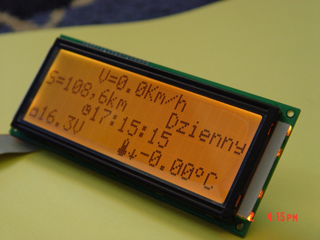
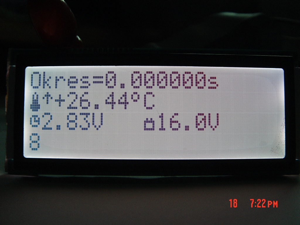
- displays speed, RTC time, accumulator voltage, total/day course, temperature on LCD 4x20
- displays speed on three 7-segments LED displays
- set up:
- wheel circumference from 0,1m to 10m
- time of: actualization of temperature, voltage, time, saving the course (0-255sec)
- saving (in EEPROM):
- wheel circumference
- time of data update
- course
- the system was adapted to LCD connection BIG with RGB backlight
- Vmax = 200km/h, Vmin = 1,8km/h
- burns the fuse when in installation a voltage more than 18V occurs
- displays the speed on big 7-segments displays
- positive LCD display 4x20 characters BIG type Using the negative displays outside is not recommended, because the sun makes them white, while the positive make ideal contrast.
- simple switching total/day course
- saving data
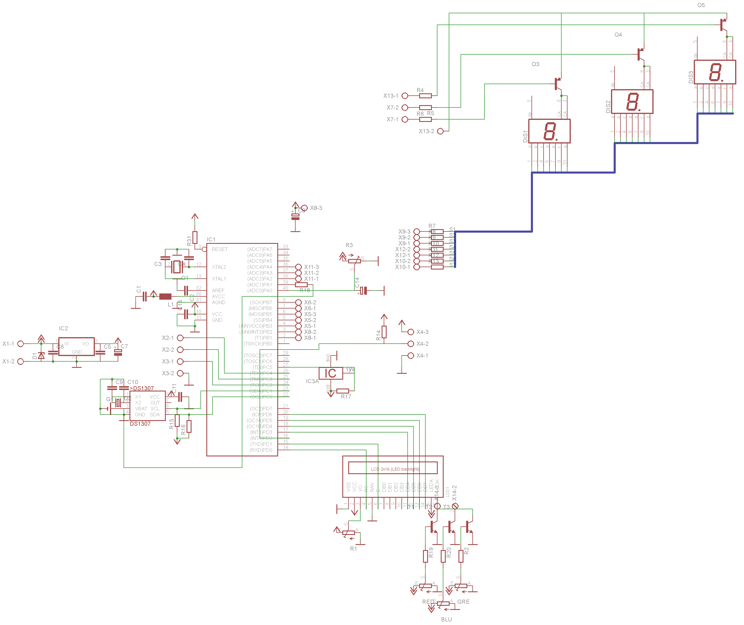
To measure the wheel rotation time, an external interrupt INT0(PD) was used. The interrupt is activated by trailing edge of unipolar hallotron sensor CS3144E. After stating the rotation of the wheel, subprogram “Interrupt” is done, where the auxiliary variable “Course” is incremented. During the loop, it is multiplied by the circumference of the wheel. This treatment was required, because Bascom can not cope with very frequent floating point calculations in interrupt. For this reason, the subprogram has to be short.
With the first impulse the timer1 is started, after the second one it is turned off. When the second impulse did not occur after 2 seconds, 16-bit counter overflows and goes to the subprogram Ovrflt1, where some of the variables and displayed speed are zeroed, so the minimum is 1,8km/h.
Menu support
The project is with the edition of settings, simple adding and deleting, so the program has the following functions: the computer is supported with PLUS MINUS SET switches, so there is no possibility of returning to the change of the values and you have to enter menu again to change it, after going to the end of the edition, the program returns to the main screen.
Using “Program” variable results in individual screens of operation appear. For example, writing to 0 variable results in displaying the main menu.
The program consists of 5 such screens:

The output screen shows all the main data:
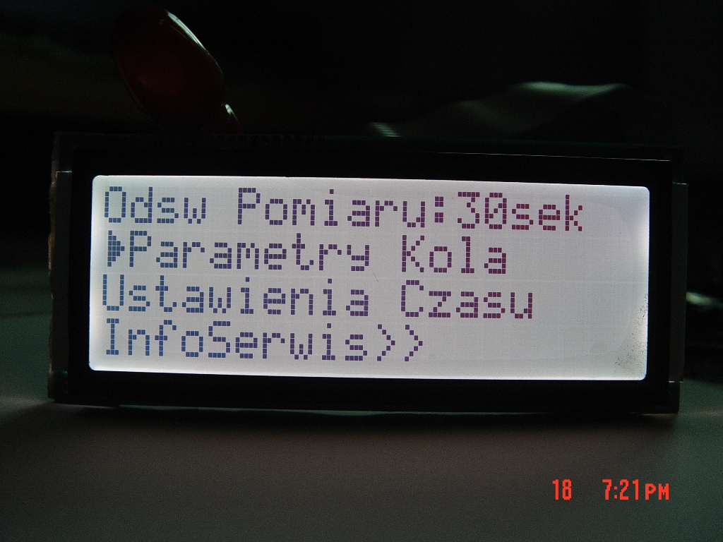
The selection screen of the program and the frequency settings of data acquisition:
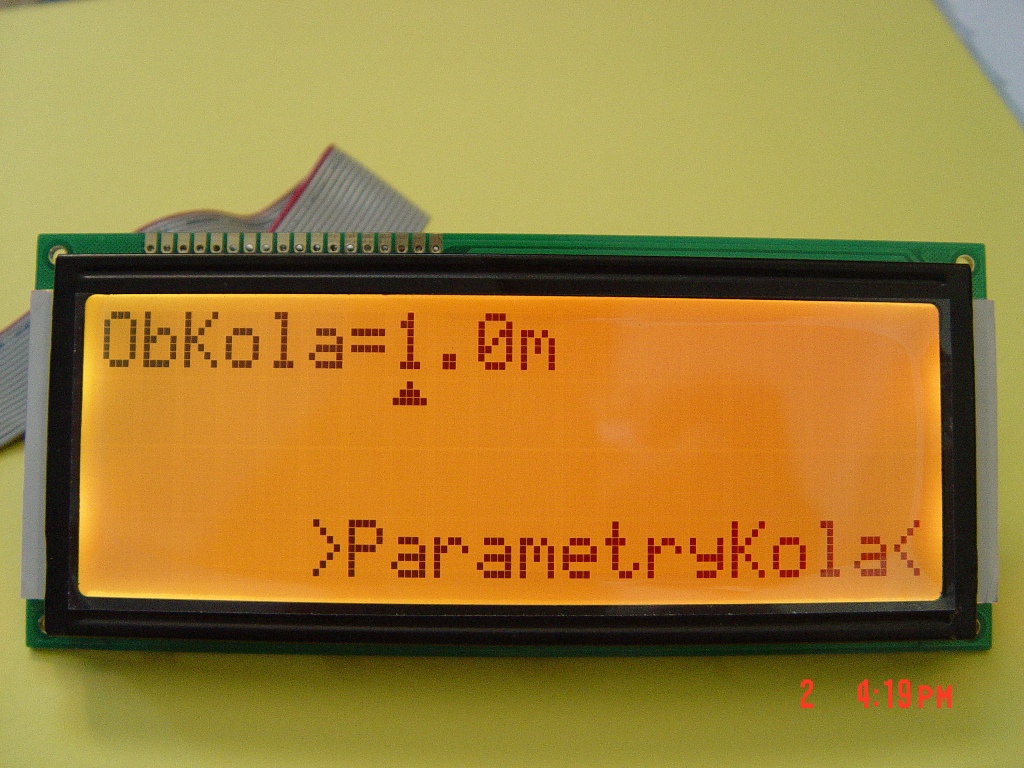
The screen of the wheel circumference change:
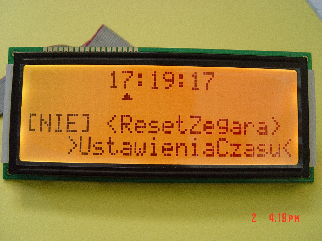
The setup and reset the clock screen:
The speedometer measures the time – the value has to be calculated to seconds, so there is a possibility of reading the period (32us-2s).
To check the status of switches, “Debounce” instruction was used, which after changing the state on the pin, goes to a subprogram, where it filtrates the data, what means checking in which program we are, the position of cursor and basis on this, adds or subtracts from the variable. It also may move the cursor position to the next value after clicking the SET, or comes back to the main screen.
Example of a simple and best way to increase or decrease the values in “multi-windows” menu.
Code:
Code:
Do*

If Program = 1 Then*
* *'/////Jakis Ekran///*
End If*

If Program = 2... Then*
* *'/////Jakis Ekran///*
* *'...*
End If*

* * * 'pullup*
* * * Debounce Pinx.x , 0 , Setting , Sub*
* * * Debounce Pinx.x , 0 , Plus , Sub*
* * * Debounce Pinx.x , 0 , Minus , Sub*

Loop*
End*

Setting:*
* *If Program = 1 Then*

* * * If Kursor < X Then "jeśli zmienna kursor jest mniejsza niż maksymalna liczba "komorek Edycji* to*

* * * * *Incr Kursor "przesuwa położenie kursora do następnej komórki edycji"*

* * * End If*

* *End If*

Return*

Plus:*
'Jeśli został wciśnięty przycisk plus następuje skok do podprogramu gdzie sprawdza się*
'jaki ekran jest wyświetlony i w jakim momencie jest kursor i która zmienna(komórkę)*
'należy zwiększać bądź zmniejszać w drugim podprogramie...*

* *If Program = 1 Then*
* * *If Kursor = 1 Then*
* * * Incr Jakas_wartosc "zwiększa wartość w komórce"*
* * *End If*
* *End If*
* *'itd*

Return*

Minus:*

* *If Program = 1 Then*
* * *If Kursor = 1 Then*
* * * Decr Jakas_wartosc "zmniejsza wartość w komórce"*
* * *End If*
* *End If*
* *'itd*

Return
The entire displaying on LCD is done by the terms “If program=x then”, conditions tables referring to the positions of the cursors (which indicate the actually operated variable and its screen) should be done in the configuration windows. After that, in subprograms minus plus set, decide what has to happen with a variable in a given position, after clicking the button.
Subprogram “Temperature”
Item “Refresh the measurement: xsec” was added to the menu, because from time to time, we need to turn off the interrupt system in order to read, and this necessitates turning the 7-segments display off for a short time. Unfortunately, the faster the temperature, voltage refresh etc., the flashing becomes more annoying.
In this subprogram, the accumulator voltage and temperature is read from DS18B20 sensor. Actualization of time is done with frequency, which was set in configuration menu “Refresh the measurement: xsec”, where x can be set from 0 to 255 with steps of 10 seconds.
Communication with the DS1307 system, what is reading the current hour, minute, second, does not happen in a loop continuously, but only once a set time. After reading the time, the value is programmatically increased in timer2 interrupt, that allows to accelerate the work of the other modules, and the deviation is corrected at certain time with the RTC system.
The temperature reading procedure is standard, supports the negative temperatures measurement service, added a trend mark.
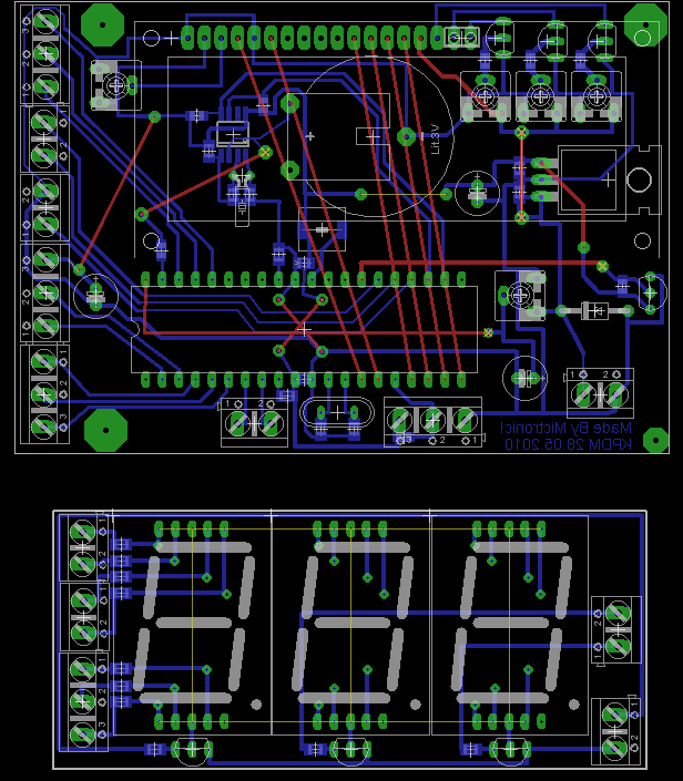
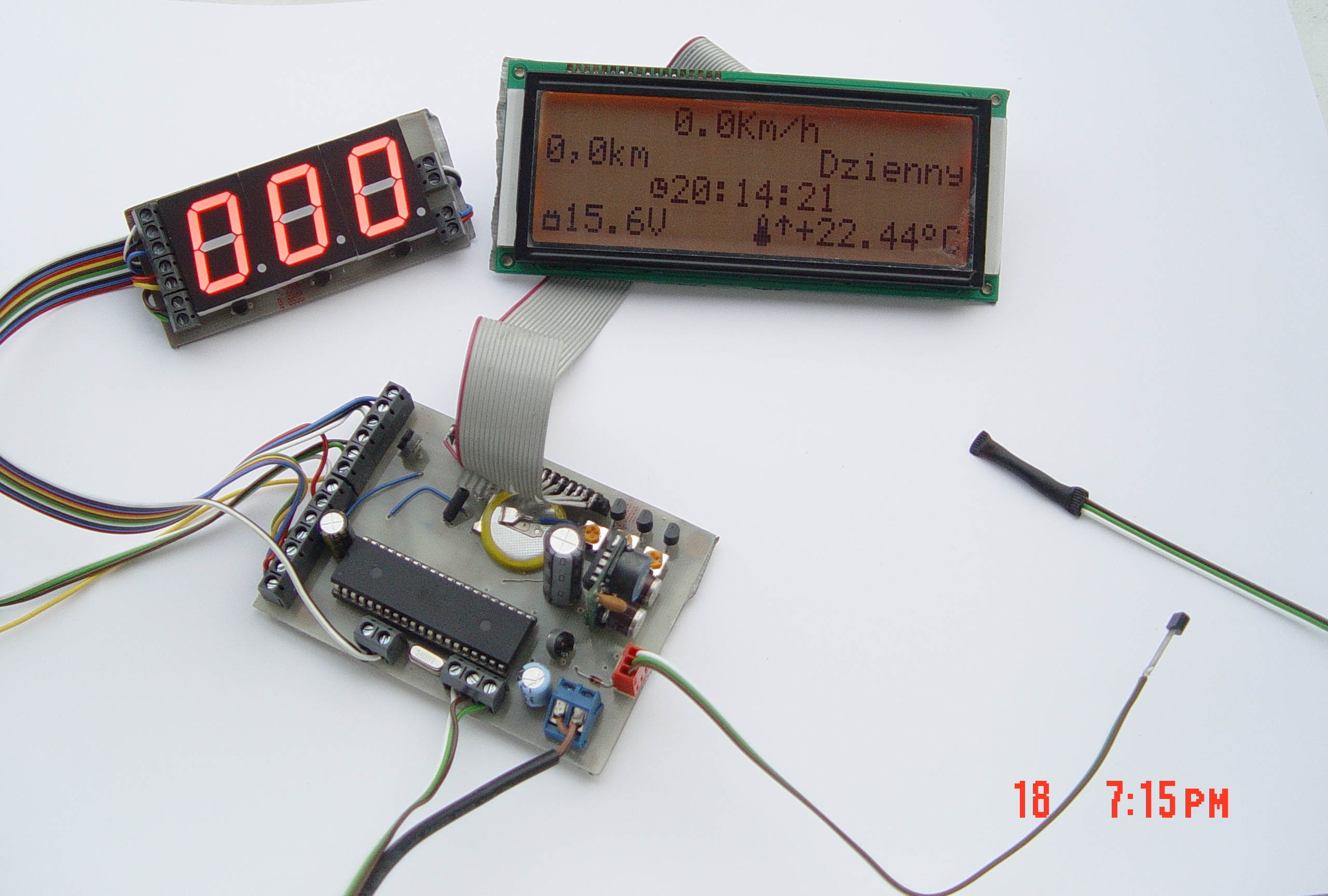
Printed board and hardware
The quality of projected program is poor. Also, the board do not match the display (so-called “sandwich”), what makes it not very aesthetic.
An impulse equivalent of a popular stabilizer of small dimensions and good parameters was used to stabilize the voltage of 5V.
Photos:


Link to original thread (attachment) – Komputerek do dwukołowca LCD+LED.
Last edited by a moderator: