Continue to Site

Welcome to EDAboard.com

Welcome to our site! EDAboard.com is an international Electronics Discussion Forum focused on EDA software, circuits, schematics, books, theory, papers, asic, pld, 8051, DSP, Network, RF, Analog Design, PCB, Service Manuals... and a whole lot more! To participate you need to register. Registration is free. Click here to register now.

Complete step by step guidance on Inverter or PV panel design

Status
Not open for further replies.

immanuel4321

Newbie level 4
Joined
Jan 1, 2014
Messages
7
Helped
1
Reputation
2
Reaction score
1
Trophy points
3
Activity points
54
I am a complete newbie to actual practical application of circuit design and electronics..So I would be very grateful if someone guided me step by step on how to design and make an inverter circuit. This is actually for a PV system I have to make..I have the panel, the transformation unit, inverter unit, converter and buffer units.
 

It is not easy make an inverter that is powered solely from photovoltaic panels.

Usually the PV panel charges a battery. Then the inverter draws current from the battery.
 

Yes sir, I believe you are absolutely right. What I am actually trying to do here is that I am trying to work on the paper I have attached. I am trying to make some changes such as which as of now are maybe change the converter type or find extra parameters to consider or atleast find some application of the paper. But I think I need to to everyting about pv systems and inverters, the design parameters to be considered why we use this component and why a converter of this type for what etc. basically everything from scratch, for which I plead you to guide me. I am ready to work hard if guided properly.Thanking you.
 

Attachments

  • A Single-Phase Photovoltaic Inverter Topology With.pdf
    773.8 KB · Views: 193
This project is not easy for a newbie.

You can expect to have to wind your own step-up transformer, from raw materials (unless you are very fortunate to have access to one which performs to your specs). You can expect to unwind and rewind mistakes, or else make a second or third one.

You'll need to decide whether you want the output to be sine waves, modified sines, or square waves.

You'll need to design your inverter to accept a wide range of supply voltages (from the PV panel), and convert it to a fixed level of high voltage AC.

It will consist of several stages, all of which you must adjust so they operate properly. Expect to burn up a few components in the process.

Many a glitch and 'gotcha' lie in wait.

This is really the equivalent of a college course. You would need someone knowledgeable at your workbench.

You can find several discussions about inverters at this board. Look at the bottom of this page to see a list of some threads.
 
I know this might be a bit of a shock for you..but I am a college student. But anyways I am ready to learn and work for it. So right now before I think about circuit designs I have to find what kind of input and output I need. What are the parameters I have to consider and their values. But I have one big doubt. How should I know which circuit I should go for..as in for eg: the paper chooses a full bridge inverter and a cycloconverter. Is there a specific parameter they focused on for choosing it? Will I be able to choose what kind of converter or inverter I need depending on the parameters?
But as of now I think I am going to start from the input by fixing the ratings for my panels and the battery banks. The next stage I think is the transformation stage. So please tell me what should I consider for deciding the transformer design and further steps. I shall keep you posted about my work.
I am really grateful because you have helped me kickstart my project work. I hope to get further help from you.
 

How should I know which circuit I should go for..as in for eg: the paper chooses a full bridge inverter and a cycloconverter. Is there a specific parameter they focused on for choosing it? Will I be able to choose what kind of converter or inverter I need depending on the parameters?

It requires more work to get AC sinewave output. There are various methods such as filtering, or PWM. It's probably a toss-up as to which you would find easiest to construct, or to regulate, or which is most efficient.

So you must weight all factors to determine whether you want square waves or sine waves or modified sines. Your transformer step-up ratio may be different, depending.

* How much power do you need?
* Is your load variable or unchanging?
* Can your load tolerate 120V square waves?
* Is your load an AC motor (which runs best on sine waves)?
* Do you intend to sell electric power to the utility company?
Etc.

But as of now I think I am going to start from the input by fixing the ratings for my panels and the battery banks. The next stage I think is the transformation stage. So please tell me what should I consider for deciding the transformer design and further steps. I shall keep you posted about my work.
I am really grateful because you have helped me kickstart my project work. I hope to get further help from you.

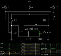
Here is a simulation showing the basic concept of a square-wave inverter (greatly simplified).

The switching devices would be replaced by transistors / mosfets.


In regard to design and construction of a transformer, this thread may be helpful.

https://www.edaboard.com/threads/229615/
 

Its been a long time...after a long time of researching with my base paper..
I have decided upon a full bridge inverter linked to a matrix converter using mosfet as the switch
 

Status
Not open for further replies.

Similar threads

Part and Inventory Search

Welcome to EDABoard.com

Sponsor

Back
Top