Continue to Site

Welcome to EDAboard.com

Welcome to our site! EDAboard.com is an international Electronics Discussion Forum focused on EDA software, circuits, schematics, books, theory, papers, asic, pld, 8051, DSP, Network, RF, Analog Design, PCB, Service Manuals... and a whole lot more! To participate you need to register. Registration is free. Click here to register now.

Comparison of 89sXX programmer circuit

Status
Not open for further replies.

netdeamon

Newbie level 6
Newbie level 6
Joined
Jun 7, 2013
Messages
14
Helped
0
Reputation
0
Reaction score
0
Trophy points
1,281
Visit site
Activity points
1,396
I got struck between these two links that show circuit for programming 89SXX.

1. In LINK 1 this link, the pin number 23,12,10,9,7,5,2 are used of DB 25 connector.
While in this link, pins 5,6,7,8,9,10,18 are used of DB 25 connector.
So which one of the DB 25 version is correct? Or both are correct?

2.The author has said that USB is used to supply 5 V, 100 mA current. But instead of cutting a USB cable and using it, can't we use a 5V source from a battery of 9 V?

3.I had some doubts about connection in this circuit , so I modified the circuit as follows.
Is the changes I made in circuit wrong?
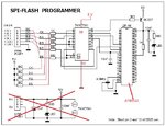
ISP-Flash Programmer.jpg

4. Can I replace the 4 MHz clock with 11.0592 MHz in LINK 1.
 
Last edited:

Its not a hard question. I know many people have made circuit from the above links, I am just struck in between.

If you have made circuit, or have any info then please answer the question.

If my question requires further details or further clarification then tell me, I will post it.
 

I got struck between these two links that show circuit for programming 89SXX.

1. In LINK 1 this link, the pin number 23,12,10,9,7,5,2 are used of DB 25 connector.
While in this link, pins 5,6,7,8,9,10,18 are used of DB 25 connector.
So which one of the DB 25 version is correct? Or both are correct?

2.The author has said that USB is used to supply 5 V, 100 mA current. But instead of cutting a USB cable and using it, can't we use a 5V source from a battery of 9 V?

3.I had some doubts about connection in this circuit , so I modified the circuit as follows.
Is the changes I made in circuit wrong?
View attachment 92856

4. Can I replace the 4 MHz clock with 11.0592 MHz in LINK 1.

1. Pin 18 to 25 all are ground, so you can use any pin. Check the circuits again, both circuits are same and the only difference is a buffer inbetween and ground pins changed.

2. Yes, you can use external power supply, but dont forget to short the ground pins.

3. The circuit seems to be for AVR and not s52.

4. Yes, you can use any crystal above 4MHz.
 
Is the buffer 74HCT541 really needed? The author in LINK 1 has shown a simple circuit without buffer though he has recommended buffer to be used for begineers. But the above circuit is very simple and I think the buffer adds unnecessary complications.

And I think both the circuits are for 89S series as the author have mentioned in text.
I have never used the DB 25 connector, but I have one port in old pc with a old printer cable. So I am planning to use it.
Pin 18 to 25 all are ground, so you can use any pin
What I didn't understand is that the pin number mentioned are different, so what is similarity between them.
 

I always recommend a buffer to protect the computer port.

Look at this link **broken link removed**
 

Status
Not open for further replies.

Similar threads

Part and Inventory Search

Welcome to EDABoard.com

Sponsor

Back
Top