Continue to Site

Welcome to EDAboard.com

Welcome to our site! EDAboard.com is an international Electronics Discussion Forum focused on EDA software, circuits, schematics, books, theory, papers, asic, pld, 8051, DSP, Network, RF, Analog Design, PCB, Service Manuals... and a whole lot more! To participate you need to register. Registration is free. Click here to register now.

Comparator with timing

Status
Not open for further replies.

zuser999

Newbie level 6
Newbie level 6
Joined
Jul 8, 2013
Messages
12
Helped
0
Reputation
0
Reaction score
0
Trophy points
1
Location
LA
Visit site
Activity points
99
Hello,

I want to implement a comparator that will have Vcc as an output only when an input goes more than a threshold for more than a certain amount of time. That is, if the input is greater than the threshold but it was applied for less than the required amount, the output would not go to Vcc. How can we implement this?

Thanks
 

Just put an RC time delay in the path of your input signal. After this delay, it will reach the threshold point of the comparator.
 

Actually, depending on exactly how you want the circuit to behave, you might need to use two comparators. One interpretation: The first comparator would trigger immediately, whenever the input was above the threshold. The output of that comparator should be used to start the timing circuit, when the input goes above threshold, and should reset the timing circuit to "zero" whenever the input is not above threshold. A second comparator would accept the timing circuit output and trigger when its threshold was reached. The details of the circuit between the comparators would still need to be worked out.

You didn't say whether or not the output should latch, or under what conditions it should reset. That behavior should be better-defined.

No the output should not latch and it should reset when the voltage goes down the threshold voltage. It's like you have a push button with one pin connected to Vcc and the other to the non-inverting pin of the comparator. When the push button is pressed for a couple of uS, let's say 20uS, the output of the circuit will be high. When the push button is unpressed, the circuit changes state immediately and goes to low.

Also time-delay is important. Are we talking about us, ms, s, min..

We are talking about uS.

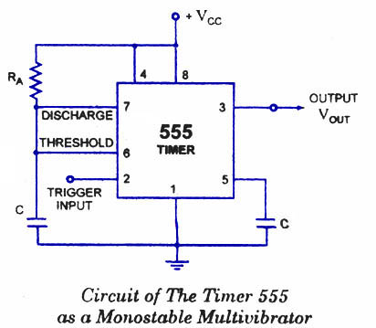
555 not gate followed by 555 monostable multivibrator is what you need..

Can you please further emphasise.


Thank you

- - - Updated - - -

Just put an RC time delay in the path of your input signal. After this delay, it will reach the threshold point of the comparator.

You think this will be accurate enough? Where will this RC discharge? I have a continuous signal with high slew rates.
 

Use the following two stages the 555 Not gate will respond to the 2/3Vcc as thresold

and the monostable multivibrator is for desired time delay

**broken link removed**

555-monostable-multivibrator.jpg
 

This again demonstrates the importance of stating your problem fully at the outset. Now a few post later we learn about uS timing, hight slew rates and other things that crawl out of the wood work. If you want solutions for a problem STATE IT CLEARLY WITH ALL REQUIREMENTS otherwise you are wasting everybody's time. Not doing so suggests laziness and sloppy-ness.
 
Last edited:

I don't see which part of my problem is unclear. I will repeat the problem in detail.

I want to make a circuit, that has a supply of Vcc, that basically acts as a comparator but with some timing.
If the input voltage is higher than the threshold voltage for a specified time (let's say about 100uS), the output will go to Vcc. But if the input doesn't stay high for 100uS, and only stays for 50uS, the output will not change and will stay 0. The rest of the details are common to basic comparator circuits.
 

I had something very similar to this one. I'm sorry if I hadn't expressed my thoughts clearly. I hope the outline of the problem is clearer now.

Thanks :)
 

No the output should not latch and it should reset when the voltage goes down the threshold voltage. It's like you have a push button with one pin connected to Vcc and the other to the non-inverting pin of the comparator. When the push button is pressed for a couple of uS, let's say 20uS, the output of the circuit will be high. When the push button is unpressed, the circuit changes state immediately and goes to low.


<snipped>

From what I have quoted above, at least, your requirement is possibly still somewhat unclear. The reason I thought that you might need a pure threshold detector followed by a timing circuit and then another threshold detector, instead of something based on a plain RC for triggering a threshold detector, is the possibility that the RC-type response could trigger if the switch was opened when the RC's output voltage was near (but not yet AT) the voltage threshold that would indicate that the required time had passed, but the time-delay requirement was not quite satisfied, and then the switch was closed again for a time shorter than the required delay, but the RC was still charged sufficiently that it more-quickly reached the threshold. According to one possible interpretation (the one I used), that would fail to meet the requirements.

And I assumed that it might be a signal source, rather than a pushbutton switch, that might change its level rapidly. I also guessed then assumed, without the requirement having been defined properly, that you really did want to require that the full specified time should pass, after every time the signal went below the threshold voltage and then back above it, before the output would be triggered.

As others have begun to mention, there are lots of ways to implement the requirements. But the requirements must be accurately defined, at least giving the required output behaviors in terms of all possible behaviors of the input.
 

Yes it is a signal source that has pulses in the uS range. I just gave the example of a push button to clarify some points. What other requirements are still unclear and you think I should talk more about?

And also the application that I'm working with is time sensitive in the uS range. That is, inserting an RC circuit might delay the input to the comparator and yield not so accurate results

As for the outputs:

When input is less than threshold output is 0.

When input is higher than threshold for a certain period of time, output is Vcc as long as input is higher than threshold.

When input is higher than threshold for but for a period of time less than the required timing, output is 0.
 
Last edited:

<grin!> Well, if I define some requirements, then you might not get what you want. Seriously, though, I think that only you can imagine all of the possible requirements, unless you give us more information about what you are trying to accomplish, i.e. details of the application. Otherwise, you just have to try to imagine every possible state that the system might ever be in, and decide how it should behave from that moment forward. And that is only one type of requirement. Others might include typical/max/min voltage and current amplitudes/slew-rates/noise/ripple for inputs, outputs, and supplies, operating temperature range, required accuracy and precision, desired failure rate, shock and vibration survival requirements, production cost, size, weight, power consumption, mean time to repair, acceptable levels of electrostatic discharges it could absorb, safety requirements (e.g. does it need to be electrically safe around people, fuel, explosive ordinance, explosive gas atmospheres, et al, and if it burns in your vehicle will the gases be poisonous to you?), radiation hardness, electromagnetic compatibility (i.e. acceptable levels of both conducted and radiated interference, both incoming and outgoing), human usability factors (e.g. does it need to be able to be used while wearing arctic gloves?), stealth disciplines (does it need to not shine a display or make a beep when you are doing covert ops at night, surrounded by armed enemies?), disposability/environmental protection (no dangerous metals allowed?), and so on. And there are many more. Only some will be applicable and maybe only a few will be important. It all depends on the application.
 
Last edited:

Depending on what you are most comfortable with, and what your requirements are, a digital circuit might even be the easiest/smallest/cheapest/best implementation.
 

Here is a very basic concept idea without using a micro (may be easier though), based on a stable clock for setting the time that the input signal must be above the required threshold.

The comparator opens the counting gate to (U2: 4017). It also set the logic to enable (U5: 4013) to be set by the output from the counter. The specific count is selected by the DIP switch.
If there is a count while the TRIG signal from the comparator is still high, the Q output (OP) will be set high. It will stay high until TRIG goes low again.

In the second timing diagram, TRIG goes low before Time(min) goes high and as a result the output (OP) stays low. The resolution to which the timing can be set is one clock cycle of the 100kHz clock. This clock may be selected to suit the application but higher clock frequencies will require longer counting cycles.

The comparator threshold is set to 2.5V in this example.
 

Attachments

  • comp_dly.gif
    comp_dly.gif
    42.1 KB · Views: 126
Last edited:

Status
Not open for further replies.

Similar threads

Part and Inventory Search

Welcome to EDABoard.com

Sponsor

Back
Top