benbiles
Member level 4

- Joined
- Jan 24, 2014
- Messages
- 76
- Helped
- 0
- Reputation
- 0
- Reaction score
- 0
- Trophy points
- 1,286
- Activity points
- 2,146
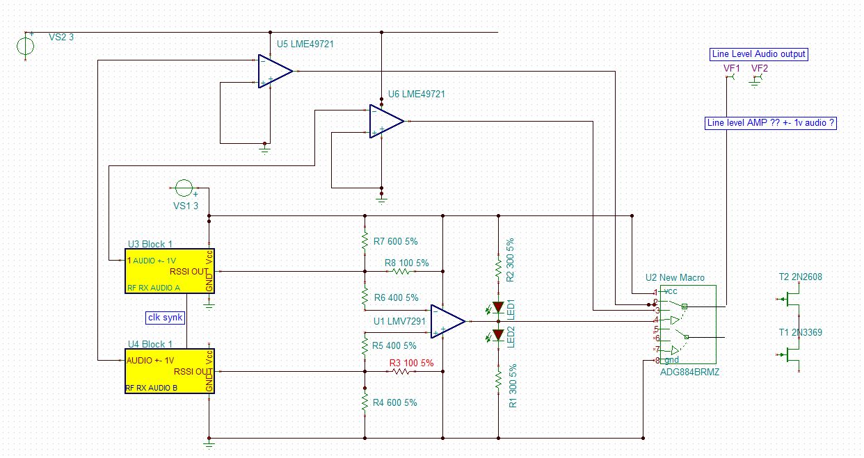
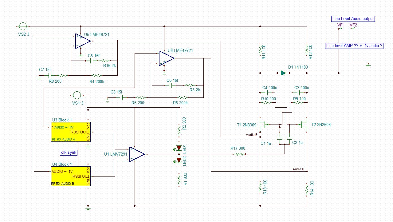
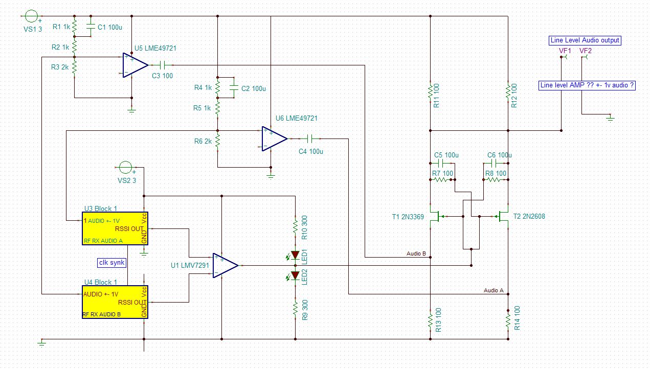
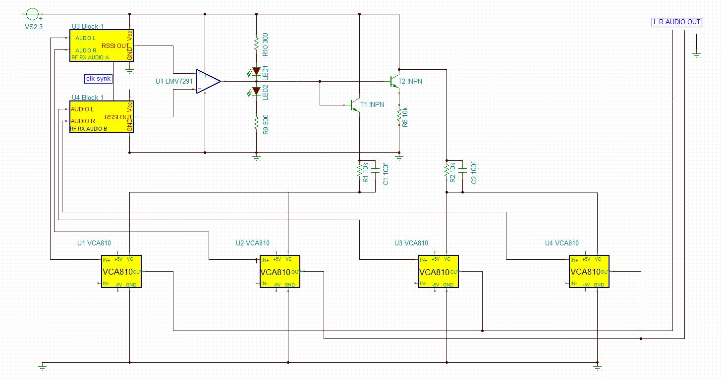
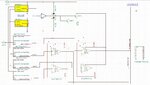
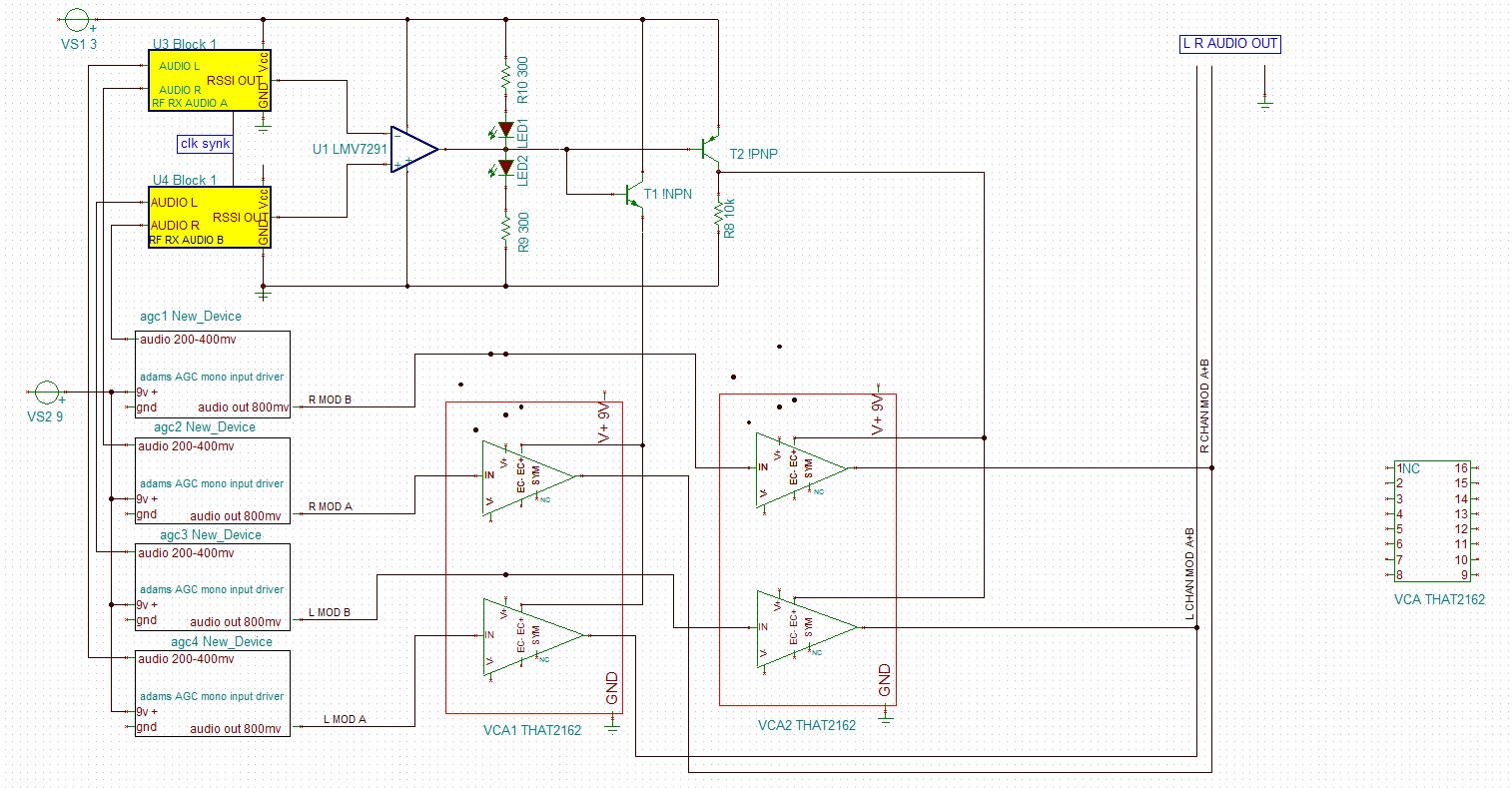
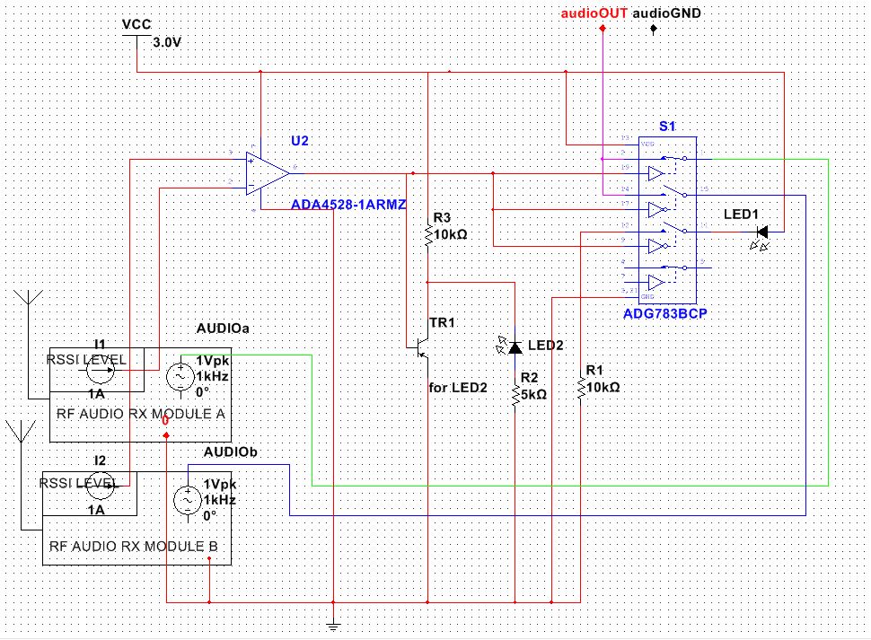
Hi, I am trying to understand how to use an OP AMP to compare two changing DC voltages of a RSSI ( receive strength signal indicator ).
I would like the audio outputs of two RF modules to flipflop to the higher RSSI DC voltage using a quiet switch IC as in the schematic..
I would ultimately like a delay to be set between the flipflop and then eventually I would like to change the flipflop switch to a more subtle fast pan
between the audio outputs of the modules.
But !! I feel I am running way ahead of myself on the OPAMP area of this design in progress !!
Do I need to use some resistors here to set some input parameters for the two DC inputs ? do I have this completely wrong !! should I be using two or even for OPAMPS ?
should I be using two schmitt triggers somehow to smooth things out if the RSSI voltage is erratic?
The Voltage will rise and fall from 1-3 vdc on either input depending on how strong the receive signal will be. However if the two voltages become too similar then it would be useful for the flipflop to latch for a given time.. ( wait for a stronger signal difference between the two voltages )
any ideas would be welcome.. I would like to avoid using a micro controller if possible since the dual receiver will be run on battery.
The LED lights are supposed to show which module is currently being output..
Thanks,
Ben
Last edited:

") In either case, you can use resistors to add additional hysteresis to the comparator, so you don't need a schmitt trigger.
In either case, you can use resistors to add additional hysteresis to the comparator, so you don't need a schmitt trigger.