Continue to Site

Welcome to EDAboard.com

Welcome to our site! EDAboard.com is an international Electronics Discussion Forum focused on EDA software, circuits, schematics, books, theory, papers, asic, pld, 8051, DSP, Network, RF, Analog Design, PCB, Service Manuals... and a whole lot more! To participate you need to register. Registration is free. Click here to register now.

Common Transistor Amplifier:- doubts on Input impedance

Status
Not open for further replies.
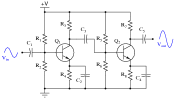
For the shown circuit, it is true.
But Rload may be different or is chosen according to your application.
There is two things, If it is capacitive loading, or resistive loading.
For Capacitive loading , Rload = Rc ( most of the time)( for dc application)
For resistive loading, Rload = Rc||RL

For example,if im going to hook up that circuit output to next stage and that stage has 12K input impedance,then (Rload=Rc||RL) = 6K||12K(next stage input impedance) = 4K ohms output impedance

then i could calculate the Cout using the 4K ZOut value???

or as LvW said, to calculate Cout, its Rc+Rload so its 6K+12k=18K Zout and 18K can be used to calculate Cout??
 
Last edited:

then i could calculate the Cout using the 4K ZOut value???
Yes correct.
or as LvW said, to calculate Cout, its Rc+Rload so its 6K+12k=18K Zout and 18K can be used to calculate Cout??
Ah..you are bit confused again. LVW was right for that case.
You output impedance will always be Rc||Rload

---------- Post added at 10:06 ---------- Previous post was at 10:01 ----------

One doubt Qube? Due you understand a coupling capacitor connected at the ouput stage, means?
If yes, then As stated LVW, your high pass cut off frequency should be calculated by adding Rc in series with capacitor and load resistance.
 

Yes correct.
Ah..you are bit confused again. LVW was right for that case.
You output impedance will always be Rc||Rload

---------- Post added at 10:06 ---------- Previous post was at 10:01 ----------

One doubt Qube? Due you understand a coupling capacitor connected at the ouput stage, means?
If yes, then As stated LVW, your high pass cut off frequency should be calculated by adding Rc in series with capacitor and load resistance.

i think Cout is used to block DC from a amplifier stage from passing to another stage and interfering with its bias point..
and it is also used as high pass filter to attenuate signals which are less than cut off frequency...

So the output impedance of a common emitter = Rc||Rload... and the Cout value is chosen using Cout=1/(2*3.14*Hz*Zout) here Zout = Rc||Rload and Rload is the next stage input impedance??
 

At collector node, all the resistance and capacitance should be in parallel.
Now, If, Rc and Rload are at the two ends of coupling capacitor; Cout will be 1/(2*3.14*Hz*Zout) here Zout = Rc+Rload
(where Rload is the input impedance of next stage)
If, Rc and Rload is connected to the collector of transistor, then at this end equivalent resistance will be Rc||Rload. Capacitor may be bypass/coupling capacitor.
Bypass case Cout=1/(2*3.14*Hz*Zout) here Zout = Rc||Rload.
Coupling case Cout = 1/(2*3.14*Hz*Zout) here Zout = (Rc||Rload)+Rload2 .(where Rload2 is the input impedance of next stage)
 
  • Like
Reactions: Qube

    Qube

    Points: 2
    Helpful Answer Positive Rating
Sorry But I doubt on my previous post. Some more analysis need to be done.
Now, If, Rc and Rload are at the two ends of coupling capacitor; Cout will be 1/(2*3.14*Hz*Zout) here Zout = Rc+Rload
i doubt in this part. Rc and Rload will create two separate poles.
If, Rc and Rload is connected to the collector of transistor, then at this end equivalent resistance will be Rc||Rload. Capacitor may be bypass/coupling capacitor.
This is valid part and proven. So this is correct.
Coupling case Cout = 1/(2*3.14*Hz*Zout) here Zout = (Rc||Rload)+Rload2 .(where Rload2 is the input impedance of next stage)
This is erronious. Need to be seen the R-C-R (PI) filter response.
 

@varun
Thanks for explaining,i think i understood something

01117x01.png


in the above circuit the first stage Zout=R3||Rload(where Rload = next stage input impedance)?

am i right??
or first stage Zout =Rc; as Rc is at one end of capacitor and Rload(i.e next stage input impedance)is on the other side of the capacitor
 
Last edited:

Dear Qube
Hi
About "(where Rload = next stage input impedance)" yes you're right .
Best Wishes
Goldsmith
 
  • Like
Reactions: Qube

    Qube

    Points: 2
    Helpful Answer Positive Rating
01117x01.png

in the above circuit the first stage Zout=R3||Rload(where Rload = next stage input impedance)?
am i right??
Zout=R3||Rload, This is correct when Rload = XC3+Rload2 (where Rload2 = next stage input impedance)(XC3 is impedance of coupling capacitance C3)
 
  • Like
Reactions: Qube

    Qube

    Points: 2
    Helpful Answer Positive Rating
Zout=R3||Rload, This is correct when Rload = XC3+Rload2 (where Rload2 = next stage input impedance)(XC3 is impedance of coupling capacitance C3)

so you'll calculate the impedance of a capacitor for the frequency which will pass through it using the Capacitive Reactance formula?
 

so you'll calculate the impedance of a capacitor for the frequency which will pass through it using the Capacitive Reactance formula?
Correct, For pass band frequencies, capacitance impedance will be low compared to Rload2(where Rload2 = next stage input impedance). other freq. , it will be very high.
 

Status
Not open for further replies.

Similar threads

Part and Inventory Search

Welcome to EDABoard.com

Sponsor

Back
Top