dcwebaccount
Newbie level 3
please help, i have a question for control both n-channel mosfet to cut off discharge and charge for battery protection.
i already google this for a month without any solid solution, seem that none is care about control low side n channel for battery protection since it is mostly built-in protection IC ...
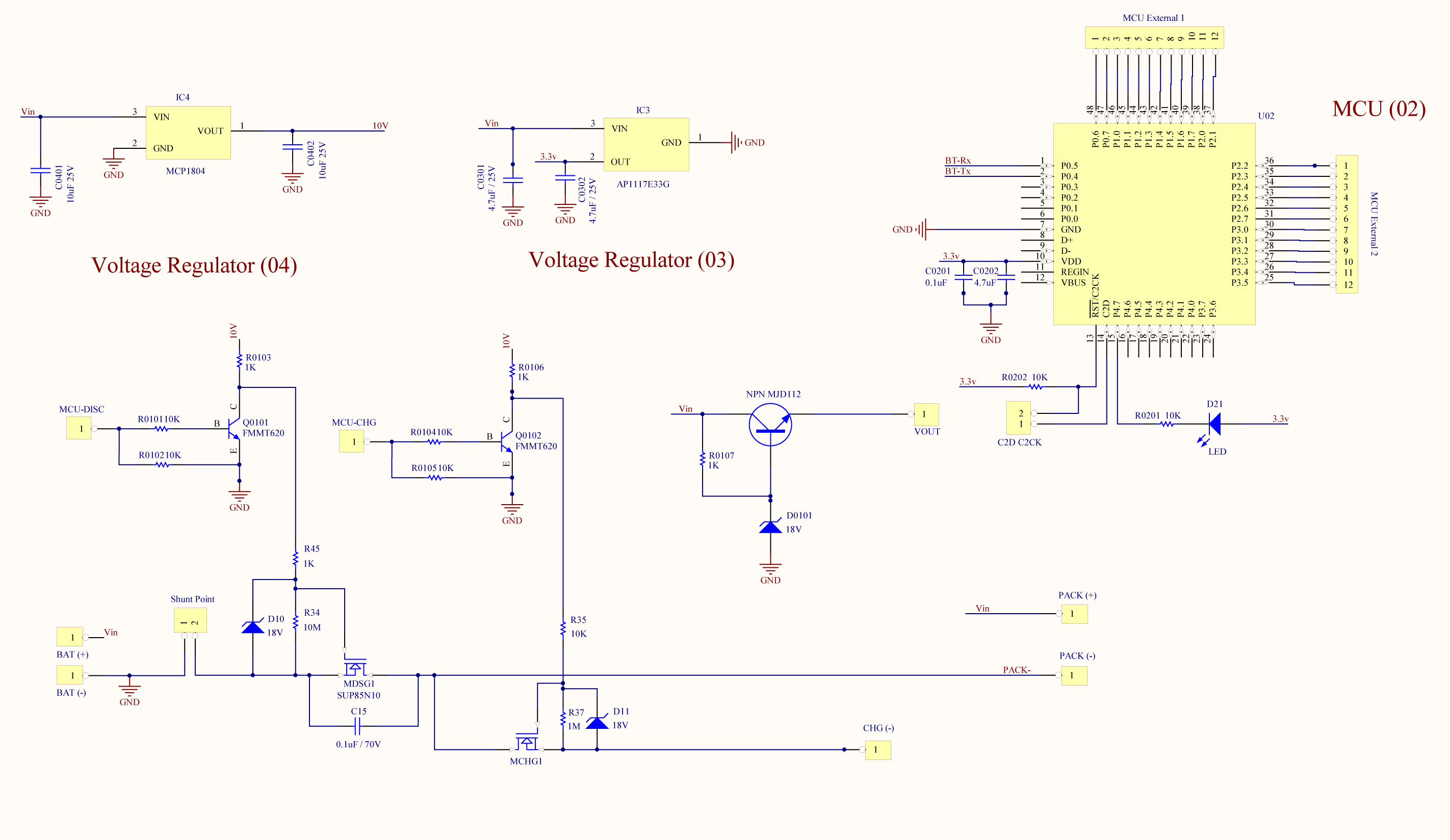
on controlling the discharge current, i just simply put the MDSG1 mosfet gate voltage Vgs high or low (to ground) for open or shutdown the path, however my problem is, when i want to close the MCHG1 mosfet for stop the Charge current (over voltage when charging my battery connected on left hand side), i don't know where to put my Vgs low enough to shutdown / turn off the MCHG1 mosfet !
last night i realized the potential between CHG(-) and BAT(-) were different that caused the Vgs of MCHG1 turn off automatically, unless i connect the Gate wire of MCHG1 to the CHG(-) point make Vgs = 0v, but the point is ... only single ground of the circuit can have right ? if the ground on CHG(-) as well that's mean the charge mosfet is disable function.
please help !!!!!
i already google this for a month without any solid solution, seem that none is care about control low side n channel for battery protection since it is mostly built-in protection IC ...
on controlling the discharge current, i just simply put the MDSG1 mosfet gate voltage Vgs high or low (to ground) for open or shutdown the path, however my problem is, when i want to close the MCHG1 mosfet for stop the Charge current (over voltage when charging my battery connected on left hand side), i don't know where to put my Vgs low enough to shutdown / turn off the MCHG1 mosfet !
last night i realized the potential between CHG(-) and BAT(-) were different that caused the Vgs of MCHG1 turn off automatically, unless i connect the Gate wire of MCHG1 to the CHG(-) point make Vgs = 0v, but the point is ... only single ground of the circuit can have right ? if the ground on CHG(-) as well that's mean the charge mosfet is disable function.
please help !!!!!
")