anasim
Newbie level 3
Combining independent boost and buck converters...
Hi,
I'm currently considering several different approaches of building a buck-boost converter to power an automotive engine management system.
However, there are several different approaches around and I'm wondering if the following would work out well...
Is it a good idea to combine a pre-boost converter which brings the input voltage to a somehow stable voltage (e.g. about 7 to 9V) and a post-buck converter which brings the final output voltage back down to 5V (which is the actual target voltage).
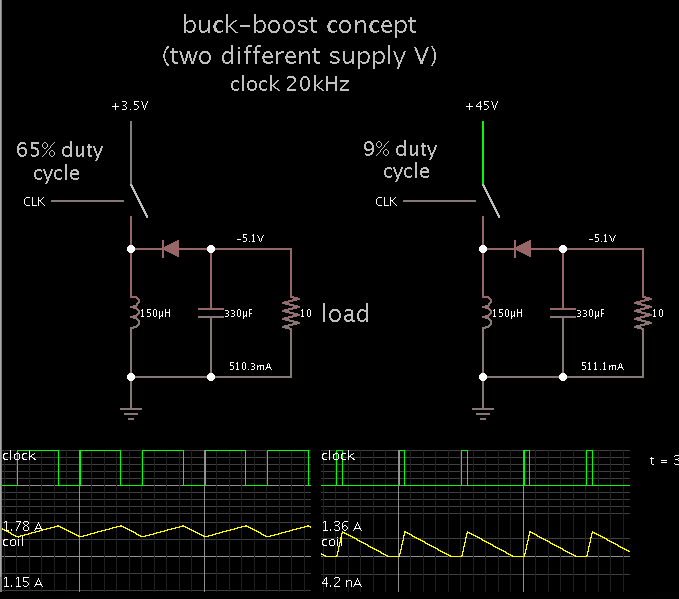
The over-all input voltage may vary from 45V (e.g. load dump) down to about 3.5V (cranking). The advantage seems to be that the regulation etc seems less complex if two "of the shelf" standard solutions are combined. Or do I've to expect any undesired regulator interactions from one stage to the other?
An additional advantage of having a stand-alone boost converter would be that a somehow stable intermediate voltage would exist for powering some start-up elements. I guess the start-up scenario of a combined buck/boost solution would be more complex...
Any experiences with systems like this?
Many thanks in advance for your support,
anasim
Hi,
I'm currently considering several different approaches of building a buck-boost converter to power an automotive engine management system.
However, there are several different approaches around and I'm wondering if the following would work out well...
Is it a good idea to combine a pre-boost converter which brings the input voltage to a somehow stable voltage (e.g. about 7 to 9V) and a post-buck converter which brings the final output voltage back down to 5V (which is the actual target voltage).
The over-all input voltage may vary from 45V (e.g. load dump) down to about 3.5V (cranking). The advantage seems to be that the regulation etc seems less complex if two "of the shelf" standard solutions are combined. Or do I've to expect any undesired regulator interactions from one stage to the other?
An additional advantage of having a stand-alone boost converter would be that a somehow stable intermediate voltage would exist for powering some start-up elements. I guess the start-up scenario of a combined buck/boost solution would be more complex...
Any experiences with systems like this?
Many thanks in advance for your support,
anasim
Last edited: